Most electrospinnings are carried out using high voltage direct current (DC). However, high voltage alternating current (AC) has also been shown to be able to electrospin fibers [Kessick et al 2004]. An additional parameter when using AC high voltage for electrospinning is the frequency of the current. When the frequency is too high, the transfer of charges or mobility of the ion may not be fast enough to sufficiently charge the solution for electrospinning. For each material, the frequency range for AC electrospinning needs to be determined although it is typically between 500 Hz and 1 kHz [Sarkar et al 2007]. When the frequency is too low, the electrospinning jet traveling between the tip and the collector may comprise mainly of a single polarity instead of periodic positive and negative segments.
The presence of both positive and negative segments on the electrospinning jet creates a plume of fibers as the opposing segments are attracted to one another at a distance away from the nozzle tip. Thus in AC electrospinning, the grounded collector has a lesser role to play compared to DC electrospinning. In the presence of a grounded collector, the electrospinning jet using AC would still be attracted to the grounded collector as there will be a potential difference between the nozzle and the collector. The plume of fibers would also be attracted to the grounded collector as not all segments on the fiber will be neutralized by the opposing charges. Sivan et al (2022) showed using electrospinning of polycaprolactone (PCL) nanofibers that at lower frequencies, the charged segment of each polarity will be longer and the plume was formed at a greater distance from the nozzle tip compared to higher frequencies. The plume is also larger with a lower fiber density compared to higher frequencies AC. Shorter and more frequent occurrence of segments of opposing charges in higher frequencies AC makes it easier for the opposing segments to meet one another and the plume to collapse into a denser ball of fibers. Higher frequency also leads to an increase in the number of beads and spindles on the electrospun fibers. This could be due to greater charge neutralizing effect in the presence of closer opposing charges and shorter charge segment resulting in beads formation. At even higher frequencies, the proximity of the opposing charges and shorter charge segment reduces the ability of the jet to stretch and thicker fibers with less beads are formed.
The periodicity of positive and negative segments on an AC electrospinning jet has been shown to facilitate a more stable jet formation compared to DC. When collecting on a rotating drum, the more stable AC electrospun jet produces fiber with greater alignment compared to fibers from DC [Kessick et al 2004]. However, the fiber diameter from AC electrospinning is significantly larger compared to DC electrospinning [Kessick et al 2004]. This is probably due to suppression of bending instability in AC electrospinning. In some cases, AC electrospinning has been found to produce fibers of smaller diameter than DC electrospinning.
Holec et al (2022) used both DC and AC electrospinning to produce fibers over a range of polyamides (PA 4/6, PA6, PA6/6, PA6/10, PA6/12 and PA11). As observed by prior research, AC electrospinning produces a fiber plume resulting in a bulky structure made of tangled fibers. DC electrospinning in contrast produces compact fiber mesh. Between AC and DC electrospinning, it is easier to produce fibers from lower and higher concentration solutions using DC electrospinning. This is probably due to greater and more consistent stretching force from a constant charge.
Balogh et al (2016) compared AC and DC electrospinning of hydroxypropylmethylcellulose with polyethylene oxides loaded with poorly water soluble model drug, spironolactone. Their study found that the fibers produced from AC electrospinning were much thinner than fibers produced from DC electrospinning. The difference in observation from other studies of AC and DC electrospinning may be due to the drug loaded in the solution which may be influenced by the applied charge polarity. There are some studies that showed that for some materials, its electrospinnability is dependent on the polarity of the applied charge [Read Electrospinning Polarity].
In AC electrospinning, apart from frequency, there is another parameter which is not found in DC electrospinning, and this is the waveform of the voltage applied. The waveform dictates how the voltage changes between the applied voltage. This would in turn affect the charging of the jet and the electric field profile between the spinneret and the collector. Sivan et al (2022) demonstrated how the waveform of the applied voltage affects the morphology of electrospun polycaprolactone (PCL) nanofibers. Comparing square, sine and triangle waveforms, their study showed that square waveform resulted in a larger electrospinning jet plume compared to the other waveforms. With square waveform, the switch between the opposing charges is much faster. At lower frequencies, long segments of the electrospinning jet will have the full charge and this favors greater stretching within each segment thus contributing to a larger fiber plume. At higher frequencies, beads are formed as short segments of alternating polarity reduces the stretching force and at the intersection between the two polarities where the charges are zero, surface tension would be dominant therefore beads are formed. At lower frequencies, longer segments of the same polarity induce a stretching inertia and thinning of the jet such that at the interface, the inertia and reduced solution mass discourages bead formation. Square waveform also gave the highest production followed by sine waveform and triangle waveform having the lowest production rate. This is probably due to the highest charge density in the square waveform and triangle waveform having the least.
Presence of positive and negative segments on an AC electrospinning jet has also been known to induce self-bundling of the electrospinning jet. Using AC electrospinning on polyvinyl pyrrolidone (PVP), Maheshwari et al (2009) was able to obtain spontaneous self-bundled yarn. It was observed that the jet first spreads out from the spinneret tip and subsequently converges in mid-flight to form yarn [Maheshwari et al 2009]. Maheshwari et al (2009) hypothesized that during the flight of the spinning jet, segments of the jet with positive charges will be attracted to segments with negative charges. It is important to note that unlike the observation from Kessick et al (2004), no stable jet was seen at the tip of the nozzle. The electrospinning jet immediately enters the bending instability when the solution emerges from the nozzle. Multiple jets erupting from the meniscus and higher order branching were also recorded. Increasing applied frequency was found to increase the fiber thickness and likelihood of beads formation due to reduced stretching of the jet in the presence of differing charges [Maheshwari et al 2009]. The phenomena of AC electrospinning jet to self bundle was also used by Valtera et al (2019) for the production of composite yarns comprising of a larger diameter core filament and coated by electrospinning. An advantage of self-bundling by AC electrospinning is that it does not require a designated grounded collector. Thus, a non-conducting polymer filament can be used to pass through and collect the self-bundling plume of electrospinning fibers. To produce sufficient volume of nanofibers, Valtera et al (2019) used a needleless spinning-electrode. The production rate of the polyvinylbutyral (PVB) envelope was 20 m/min, while the polyamide 6 (PA6) envelope was produced at the speed of 10 m/min.
In high production electrospinning, high voltage AC has been found to increase the productivity of bubble electrospinning. Bubble electrospinning is a form of free surface electrospinning where air was forced through the solution to form bubbles on its surface. This surface disruptions in combination with a high voltage application encourages multiple electrospinning jets to erupt from each bubble. Erben et al (2020) hypothesized that using an AC high voltage with bubbling, there would be greater hydrodynamic disruption which encourages more electrospinning jet formation on the solution surface. Their experiment showed that the productivity of electrospun poly(vinyl alcohol) (PVA) fibers using AC bubble electrospinning is much higher than conventional DC bubble electrospinning at 2.0 g/h and 0.3 g/h respectively. The diameter of the fibers produced by AC bubble electrospinning is slightly lower than that of DC bubble electrospinning. Given similar fiber quality, the performance of AC bubble electrospinning is better than DC bubble electrospinning.
Interestingly, AC has also been used to produce fiber using free-surface electrospinning.
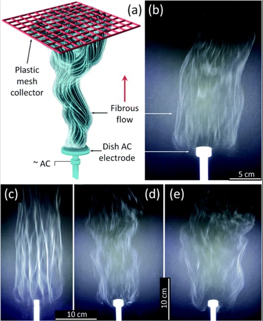
The speed at which charge accumulated on the solution to overcome surface tension and the evolution of fiber jet is very rapid. Nealy et al (2020) used an alternating current (AC) on a free surface electrospinning setup to electrospin a solution of titanium(IV) n-butoxide (Ti(OBu)4)/ polyvinylpyrrolidone (PVP), with alternating current (AC)-voltages up to 40 kV rms at 60 Hz was used. The polymer solution was fed into a shallow dish-like electrode where the AC high voltage was applied. The collector was a PTFE plastic mesh placed about 50 cm above the electrode. Dish-like electrodes with diameters from 10 to 25 mm were tested. With smaller diameter electrodes, an increase of fiber bundling was observed which is not desirable. The feed-rate of the solution was adjusted to support a stable generation of fibers. Assuming the precursor fibers were converted to TiO2, the production rate of TiO2 nanofiber from one electrode is about 5.2 gh-1. The same setup has also been used to produce zirconium titanate nanofibers [Stanishevsky et al 2023].
Published date: 05 January 2016
Last updated: 17 October 2023
▼ Reference
-
Balogh A, Farkas B, Verreck G, Mensch J, Borbas E, Nagy B, Marosi G, Nagy Z K. AC and DC electrospinning of hydroxypropylmethylcellulose with polyethylene oxides as secondary polymer for improved drug dissolution. International Journal of Pharmaceutics 2016 Article in press.
-
Erben J, Kalous T, Chvojkaac J. Ac Bubble Electrospinning Technology for Preparation of Nanofibrous Mats. ACS Omega 2020; 5: 8268.
Open Access
-
Holec P, Jirkovec R, Kalous T, Batka O, Brozek J, Chvojka J. The Potential for the Direct and Alternating Current-Driven Electrospinning of Polyamides. Nanomaterials. 2022; 12(4):665.
Open Access
-
Kessick R, Fenn J, Tepper G. The use of AC potentials in electrospraying and electrospinning processes. Polymer 2004; 45: 2981
-
Maheshwari, S., Chang, H.-C. (2009) Assembly of Multi-Stranded Nanofiber Threads through AC Electrospinning. Advanced Materials, 21, 349-354.
-
Nealy S L, Severino C, Brayer W A, Stanishevsky A. Nanofibrous TiO2 produced using alternating field electrospinning of titanium alkoxide precursors: crystallization and phase development. RSC Adv., 2020; 10: 6840.
Open Access
-
Sakar S, Deevi S, Tepper G. Biased AC Electrospinning of Aligned Polymer Nanofibers. Macromol. Rapid. Commun. 2007; 28: 1034.
-
Sivan M, Madheswaran D, Valtera J, Kostakova E K, Lukas D. Alternating current electrospinning: The impacts of various high-voltage signal shapes and frequencies on the spinnability and productivity of polycaprolactone nanofibers. Materials & Design 2022; 213: 110308.
Open Access
-
Stanishevsky A, Yager R, Nealy, S Severino C, Maniukiewicz W. High throughput fabrication of zirconium titanate nanofibers by using alternating field electrospinning. Materials Letters 2023; 330: 133318.
Open Access
-
Valtera J, Kalous T, Pokorny P, Batka O, Bilek M, Chvojka J, Mikes P, Kostakova E K, Zabka P, Ornstova J, Beran J, Stanishevsky A, Lukas D. Fabrication of dual-functional composite yarns with a nanofibrous envelope using high throughput AC needleless and collectorless electrospinning. Scientific Reports 2019; 9: 1801.
Open Access
▲ Close list