Electrospinning is initiated when the repulsive forces generated by the charges (positive or negative) on the surface of the solution reaches a critical density within an electrical field such that it overcomes the surface tension of the solution. The charges on the solution are induced by using a high voltage power supply and the voltage is usually more than 6kV. At such high voltage, a solution droplet would form a Taylor cone where electrospinning is initiated. Stretching of the viscoelastic polymer solution by the columbic repulsive forces on the jet followed by evaporation of the solvent led to the formation of fibers.
Jet Initiation
Stage 1
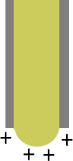
A pendent drop of solution is extruded from the needle tip. The pendent drop adopts a hemispherical profile when no charges is applied.
Stage 2
When a high voltage is applied, the charges begin to concentrate around the tip of the solution as it has largest curvature.
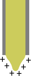
Stage 3
As the density of the charges increases with increasing applied voltage, the mutual repulsion of the molecules within the solution causes the pendent drop to contort.
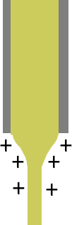
Stage 4
At a critical voltage, the density of the charges at the tip of the pendent drop and the resultant repulsive force is able to overcome the surface tension of the solution and a jet is ejected from the tip of a Taylor cone
Another method of charging the solution is to apply the high voltage to a ring around the tip of the nozzle instead of applying the voltage directly to the nozzle. Such a setup changes the electric field profile between the nozzle tip and the collector. Where the high voltage is connected to the nozzle, the electric field strength drops significantly at a few centimeters away from the nozzle tip towards the collector. However, when the high voltage is applied to a ring surrounding the nozzle, the drop in electric field strength is less steep and it maintains a base electric field strength away from the nozzle tip [Wen et al 2022]. Wen et al (2022) showed that the difference in the method of charging polyethylene oxide (PEO) solution affects the characteristic of the resultant fibers. Ring-charged electrospun fibers have a much smaller diameter that is almost half that of nozzle-charged fibers, a higher degree of macromolecular chain orientation but significantly lower crystallinity of 32%. Nozzle charged electrospun fibers have a crystallinity of 75%. Further studies are needed to determine the macromolecular chain orientation and reduced crystallinity in ring-charged electrospun fibers is due to reduction of fiber diameter or changes in the electrical field profile.
Watch video below
In most cases, creating a potential difference between the spinneret tip and the collector is achieved by direct application of the charge to the spinneret. However, it is also possible to initiate electrospinning by applying charge to the collector only [Kilic et al 2008]. The application of charges on the solution required for the initiation of electrospinning is apparently less effective when a high voltage is applied to the collector only and this results in poor spinning outcome such as larger fiber diameter and greater distribution of pore size [Kilic et al 2008].
Under certain conditions, it is possible to get precise fiber deposition with the voltage applied to the collector instead of to the solution spinneret. Coppola et al (2020) constructed an pyro-electrohydrodynamic tethered near-field electrospinning where a pyroelectric material, lithium niobate (LN) crystal plate was used to generate the electric field behind the collector. A small drop of poly(lactic-co-glycolic acid) (PLGA) solution was placed at a distance of less than 1 mm from the crystal plate. Heating of the lithium niobate (LN) crystal plate generates charges and at sufficiently high voltage, a single stable electrospinning jet would erupt from the PLGA solution droplet. The target collector would move as the fiber deposited on it to form the desired structure. The resultant fiber has a diameter between 10µm < d < 30µm. The precision of the fiber deposition is such that the multiple layers of fibers can be stacked on top of one another. A wall made of 10 fiber layers was constructed with good superimposition and homogenous stacking, no spaces or defects.
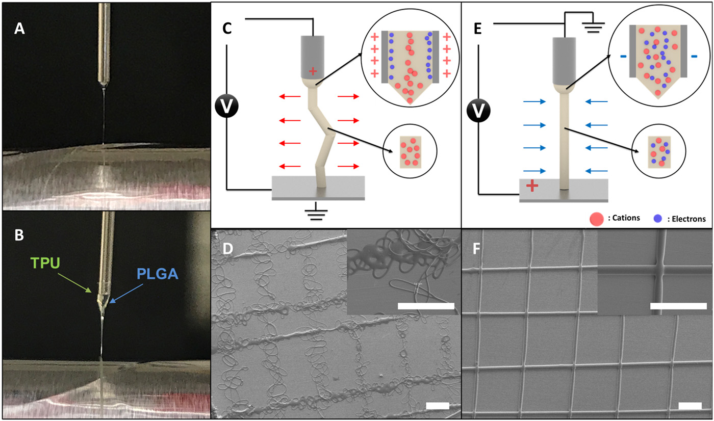
A hypothesis has been put forward by Moon et al (2021) on the longer stable phase of the electrospinning jet when the high voltage is applied to the collector instead of the needle. When a positive high voltage is applied on the collector, there is a migration of cations towards the induced negative polarity needle wall. However, as the movement of cation is slow, the presence of both cation and electrons in the electrospinning jet reduces the net interfacial charge on it. The reduced Coulombic repulsive forces on the electrospinning that causes bending instability is less than the stabilizing inertia and viscoelastic force hence there is greater jet stability. The diameter of the fibers were about 10 µm which is large for electrospun fibers. Such larger diameter also helped in the damping of the electrospinning jet. This setup for maintaining jet stability has been tested on several polymer solutions such as TPU, PLGA, polycaprolactone (PCL) and others. Stacks of up to 90 layers of electrospun microfibers made of different materials have been demonstrated.
Mechanism of a straight jet. Digital images of Taylor cones for (A) a single-phasic microfiber and (B) a biphasic microfiber. PLGA was used for the single-phasic microfiber; PLGA and TPU were used for the biphasic microfiber. Schematic diagrams of the forces applied to the polymeric jet for (C) the conventional jetting system and (E) the CREW system. SEM images of grid patterns that are produced by (D) the conventional jetting system and (F) the CREW system. Scale bars, 300 µm. (Moon et al 2021)
Basu et al (2012) compared the influence of positive voltage application to the needle against negative voltage application to the collector on maintaining a steady electrospinning polyacrylonitrile (PAN) solution jet. In agreement with the observation by Kilic et al (2008), voltage application on the needle has a more significant effect on maintaining steady electrospinning jet than the voltage application to the collector.
Jet initiation is a combination of introducing charges to the electrospinning solution and subjecting it to an electric field. While the potential difference is the same regardless of whether the voltage is applied to the needle or the collector, acquiring of charges by the solution is dependent on where the charges are applied. When the high voltage is applied to the collector, the solution has very little charges and a much higher potential difference is required to stretch the solution. However, when the charge is applied to the solution through the needle, the solution will acquire additional electrical charges which will react strongly to small increment in the electric field. Therefore, applying an opposing voltage to the collector should only be used for facilitating electrospinning jet extension and not for jet initiation.
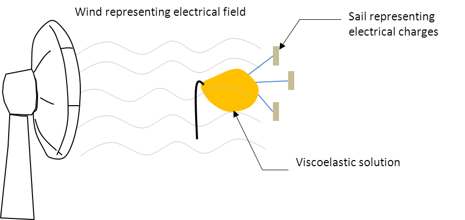
Illustration of charges and electric field on electrospinning solution
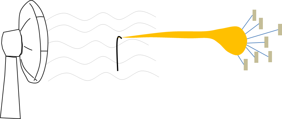
The relationship of charges and the electric field on the stretching of the solution can be illustrated by sail and wind with the sail representing the charges and the wind representing the electric field. With a viscoelastic solution attached to the sail, wind blowing against the sail will stretch the viscoelastic solution. Having more charges on the solution means having more sails to catch the wind. Any slight increase in the wind will translate to a much greater stretching force. Conversely, when there are fewer sails, a stronger wind will only give a slight increase in the stretching force.
Stronger wind but less sails will result in small increase in solution stretching
More sails to catch the wind will result in greater solution stretching
As electrospinning is being investigated as a possible method of controlled, direct-writing of nanowire across electrodes, greater attention may be paid to the profile of the jet at initiation. Under conventional spinneret-based electrospinning where the solution is being dispensed at a constant flow rate from the start, the tip of the electrospinning jet may be a big solution blob instead of a fine tip. This will compromise the precision of the nanowire at the initial point of deposition. To overcome this limitation, Xu et al (2015) used a fine needle (inner diameter: 0.21 mm) with a low initial flow rate (10 µL/hr) for electrospinning. Observation of the electrospinning polyethylene oxide (PEO) solution under high-speed camera showed that as the solution was extruded, a tiny blob was first formed at the tip of the jet. As the jet elongates, it starts to rotate around its axis of elongation under the influence of the electric field. Finally, the blob thins and formed a fine jet towards the collector.
Published date: 23 July 2013
Last updated: 16 May 2023
Basu S, Jassal M, Argawal A K. Understanding the Effect of Electrospinning Distance on the Morphology of PAN Nanofibers. The Fiber Society 2012 Spring Conference. 23 - 25 May 2012, Switzerland.
Coppola S, Nasti G, Vespini V, Ferraro P. Layered 3D Printing by Tethered Pyro-Electrospinning. Advances in Polymer Technology 2020; 2020: 1252960.
Open Access
Kilic A, Oruc F, Demir A. Effects of Polarity on Electrospinning Process. Textile Research Journal 2008; 78: 532.
Moon S, Jones M S, Seo E, Lee J, Lahann L, Jordahl J H, Lee K J, Lahann J. 3D jet writing of mechanically actuated tandem scaffolds. Science Advances 2021; 7
Open Access
Wen X, Xiong J, Sun Z, Wang L, Yu J, Qin X. A General Strategy to Electrospin Nanofibers with Ultrahigh Molecular Chain Orientation. Engineering 2022; Article in pressOpen Access
Xu L, Han W, Zheng G, Wu D, Wang X, Sun D. Initial Jet Before the Onset of Effective Electrospinning of Polymeric Nanofibers. The Open Mechanical Engineering Journal 2015; 9: 666.
Open Access