Melt Differential Electrospinning Method
Yang Weimin [yangwm@mail.buct.edu.cn], Li Haoyi, Tan Jing, Cheng Hongbo, Yan Hua, Ding Yumei
College of Mechanical and Electrical Engineering, Beijing University of Chemical Technology, Beijing 100029, China Received: 22 Jan 2015
Online: 27 Jan 2015
Unlike solution electrospinning, melt electrospinning does not require expensive scrubbing process to remove solvent vapours in the production setup. However, a melt electrospinning setup needs to address three major issues, insulation of parts from the applied high voltage, productivity and melting of the polymer feed. To address these issues, we proposed a melt differential electrospinning (MD-ESP) method [Yang et al 2014] for ultrafine fiber preparation.
 Fig 1. A schematic diagram of the melt differential electrospinning (inner-cone and out-cone nozzle). |
With the MD-ESP method, fibers with diameter smaller than one micrometer can be produced at a yield of 10-20g/h using a needleless nozzle. The process was described as follows: firstly the supplied polymer melt was distributed to the surface of umbellate (cone-like) nozzles, next the melt film covered uniformly over the umbellate circumferential surface. When the applied high voltage surpassed a critical value, self-organized multiple jets around the rim of the umbellate nozzle were ejected to the receiver plate. This process is given the name MD-ESP due to the melt flow dividing into tens of minor Taylor-cones as a result of their self-organization. A high voltage was applied directly to the collector instead of the needle or nozzle and this allows the separation of the heating system and electrodes. The design of MD-ESP spinning nozzle includes the inner-cone type and the outer- cone type [Li et al 2014a, 2014b] as shown in figure 1.
On this basis, a four-nozzle test machine was established. The basic parameters of four-nozzles test equipment is as the following:
- Polymer melt was supplied by a micro-extruder with melt flow rate ranges from 10-100g/h
- The nozzle temperature ranges from 40-400°C
- Velocity of continuous collecting line ranges from 1-100 mm/s
- Width 0.2-0.5 m
- Output 30-50 g/h
- Fiber diameter 200-6000 nm
 Fig 2. The photo of the pilot prototype of polymer melt differential electrospinning device. |
Based on the principle of polymer MD-ESP, a prototype equipment of pilot line was also designed and operated. This machine can realize mass production of polymer nanofiber by melt electrospinning route. As shown in figure 2, the equipment includes nine components: a small twin screw extruder, a melt filter, a melt metering pump, a melt differential electrospinning box, air auxiliary equipment, suction device, a lapping machine, and rolling-coiling machine. The melt differential electrospinning (MD-ESP) process and resultant diagram were compared with that of solution electrospinning(S-ESP) in figure 3.
The parameters for the pilot line and its performance are as follows:
- Integration of the 32 nozzles
- The jets number ejected from each nozzle (diameter of 26mm) range from 50 - 100
- The defined width is 0.8 m, output is 300 - 600 g/h, and the average diameter is 500-800 nm
- The thickness of non-woven fabrics is adjustable from 10µm to 1000µm
- Continuous supply of polymer melt or polymer blend melt can be realized on the pilot line
- Modularly extendable to the 6kg/h production line
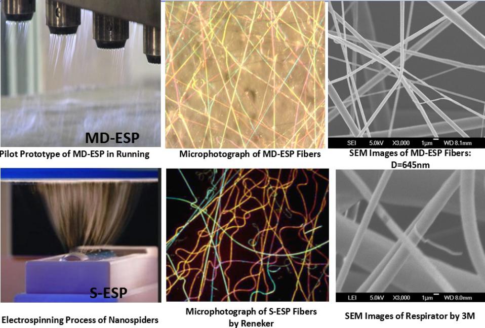 Fig 3. The spinning process of pilot line and the diagram comparison. |
Table 1 shows the material and process that have been used its corresponding average diameter.
| Material | Process | Average diameter |
|---|---|---|
| PA6 | Outer-cone nozzle | 8.85 µm |
| PET | Outer-cone nozzle | 6.37 µm |
| PLA | Outer-cone nozzle | 1.61 µm |
| PCL | Outer-cone nozzle | 1.35 µm |
| PP | Inner-cone nozzle | 645 nm |
| PLA(2002D)/PEG(200) | Inner-cone nozzle | 860 nm |
Reference
- Yang W, Li H. Principle and equipment of polymer melt differential electrospinning preparing ultrafine fiber[C]//IOP Conference Series: Materials Science and Engineering. IOP Publishing, 2014, 64(1): 012-013.
- Li H Y, Bubakir M M, Xia T, et al. Mass production of ultra-fine fibre by melt electrospinning method using umbellate spinneret[J]. Materials Research Innovations, 2014a, 18(S4): S4-921-S4-925.
- Li H, Chen H, Zhong X, et al. Interjet distance in needleless melt differential electrospinning with umbellate nozzles [J]. Journal of Applied Polymer Science, 2014b, 131(15).
