Home | About | Contact


Composite - Conductive Nanofiber and Membrane

Liu2012.jpg
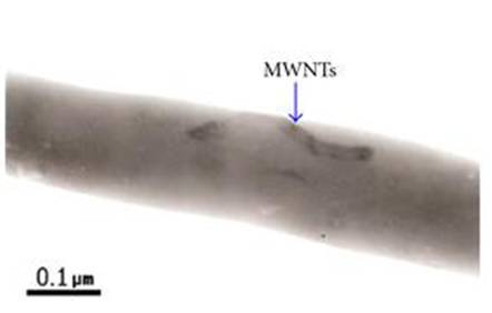
Carbon nanotube embedded within nanofiber matrix [Liu L, Pan S. Journal of Nanomaterials, vol. 2012, Article ID 610781, 8 pages, 2012. doi:10.1155/2012/610781. This work is licensed under a Creative Commons Attribution 3.0 Unported License.]

There are several ways in which electrospun nanofibers may be made conductive. One of the simplest methods is by blending conductive additive such as carbon nanotubes to the polymer solution to be electrospun [Jeong et al 2006, Chronakis et al 2006]. Other methods such as coating and sintering have also been tested. Although electrospun conductive composite fiber membrane may be less conductive than film [Laforgue et al 2007, Wei et al 2005], its conductivity per unit weight has been shown to be better on nanofibrous membrane in some cases [Laforgue et al 2007].

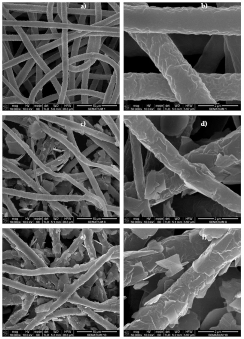
Electrospun nanofiber may serve as a substrate where conductive material is coated. The simplest form of coating involves dipping the electrospun fibers into a solution or suspension of conductive material such that the conductive material adheres to the surface of the fibers. Kang et al [2007] dipped electrospun silk membrane into a suspension of multi-walled carbon nanotube (MWCNT) in water containing Triton X-100. The MWCNT was found to adhere to the surface of the silk nanofiber and remained adhered after washing with de-ionized water. The MWCNT coated nanofiber was found to have a conductivity of 2.4x10⁻⁴ S/cm compared with 4.4x10⁻¹⁵ S/cm of uncoated fiber membrane. Francavilla et al (2021) dipped electrospun polycaprolactone (PCL) into a suspension of graphene nanoplatelets (GNPs) in ethanol to create a piezoresistive sensor. Electrospun PCL fibers may retain some positive charges on its surface and this would facilitate adhesion of GNPs on its surface. A maximum electrical conductivity value of 3.17 S/m was obtained for 2%GNPs-PCL sample but this drops to 0.08 S/m after 5 washing cycles. All GNPs-PCL samples showed high sensitivity to external pressures and excellent durability to repetitive pressing. Unfortunately, the membrane is only subjected to 5 washing cycles and it is unknown whether there will be a minimum threshold of GNPs retention after a certain number of washing.


FESEM images of (a) and (b) PCL microfibers; (c) and (d) 0.2%GNPs-PCL membranes; (e) and (f) 2%GNPs-PCL membranes. The magnifications used for these images was of 10,000x (10 µm) and 50,000x (2 µm), from the left to the right [Francavilla et al 2021].

For more reliable adhesion between the conductive material and the nanofiber template, chemical treatment may be used. Surface polymerization of pyrrrole has been used to coat the base nanofiber with a conductive layer. Granato et al [2009] doped nylon-6 nanofiber with ferric acid (oxidant salt) to facilitate the polymerization process. By introducing FeCl3 into polyethylene oxide nanofiber through blending, Nair et al [2005] was able to catalyse the vapour phase polymerization of polypyrrole on the surface of the nanofiber. The resultant nonwoven membrane was found to have conductivity in the order of 10-3 S/cm. Similar technique was employed using ferric p-toluenesulfonate (FeTS) as the oxidant incorporated into polystyrene nanofiber membrane to induce by vapor-phase polymerization of 3,4-ethylenedioxythiophene (EDOT) to form conductive Poly-3,4-ethylenedioxythiophene(PEDOT). In addition, EDOT monomer was condensed on the template polystyrene nanofiber for melt welding of the fiber to create better connectivity. The resultant membrane demonstrated a conductivity of about 1 S/cm [Nair et al 2009]. Wet polymerization has also been used to coat nylon-6 nanofiber membrane with polyaniline. This involved dipping the nanofiber membrane in aniline solution for a few hours to allow diffusion of the monomer into the fiber. The membrane was subsequently dipped in ammonium peroxydisulfate [(NH4)2S2O8] and hydrochloric acid solution for polymerization of aniline. The resultant volume conductivity of the electrospun membrane gave a value of 1.3 S/cm which compares well against plain-weave fabrics of 0.086 S/cm [Hong et al 2005].

A thin coating of gold may be formed on electrospun fibers by reduction and plating of gold salt on the fiber surface. Han et al [2006] first electrospun poly(methyl methacrylate) (PMMA) fibers containing a gold salt. Gold nanoparticles were formed on the fibers by reduction of the salt using NaBH4 and gold was plated on the surface of the fiber using the embedded gold particles to catalyse the reduction of Au3+ by hydroxylamine. During this process, the gold particles increased in size and the process was continued until a continuous coating was formed.

Blending of conductive materials into the electrospinning solution may also be used to introduce conductive property to the polymeric membrane. The interaction between the matrix and the conductive material needs to be considered for spinning of blended solution. Wei et al [2005] showed that polyaniline blended with polystyrene or polycarbonate solution when electrospun, will form along the fiber core, giving rise to a core-sheath structure. However, with poly(methyl methacrylate) and poly(ethylene oxide) solution, pockets of polyaniline dense region were formed along the fiber.

Carbon nanotubes have been blended into electrospinning solution to form nanofiber and this has been shown to improve the electrical conductivity of the membrane. For carbonized polyacrylonitrile, higher carbonization temperature gives rise to slightly better electrical conductivity due to the reduction of sp3 bond. Inspection of the electrical conductivity of aligned fibers membrane between perpendicular and parallel direction revealed no significant difference with conductivity from 0.2 to 0.5 S/cm [Ra et al 2005]. However, with multi-walled carbon nanotube added, a significant difference in the conductivity (Parallel to fiber orientation: 35 S/cm; Perpendicular to fiber orientaiton: 12.5 S/cm) was observed which suggested orientation of the carbon nanotube fillers in along the fiber alignment [Ra et al 2005]. With carbon nanotube added into a polyaniline (PANi)/poly(ethylene oxide) (PEO) nanofiber matrix, Shin et al [2008] reported a sharp increase in the conductivity of the composite when the applied voltage reached 9 V. The measured conductance was 23 times larger (2.77 uS) than the composite fiber without carbon nanotube at the same voltage. This phenomenon was attributed to self-heating of the multi-walled carbon nanotubes leading to thermal annealing of the polymer matrix which facilitated the charge transfer between the carbon nanotube and PANi.

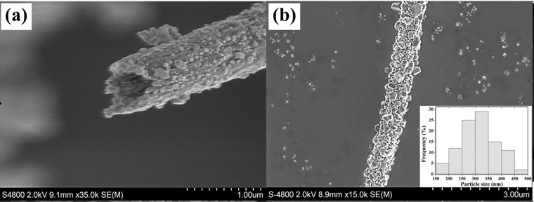
Inorganic materials generally yield much better conductivity than organic materials. Incorporation of additives and understanding of the conductive characteristic may further improve the conductivity of the inorganic fibrous membrane. Carbonized polyamic acid fiber membrane with fiber diameter 1 to 2 um was found to give conductivity of 2.5 S/cm. For smaller diameter fibers of 80 nm and subjected to compression, the conductivity rises to 16 S/cm. The author hypothesized that this sharp increase in conductivity was due to formation of more fiber junctions in the membrane with fiber of smaller diameter containing more junctions [Xuyen et al 2007]. Hyun et al [2010] constructed a highly conductive SrRuO3(SRO)–RuO2 composite nanofibre membrane with single nanofiber conductivity of 476 S/cm and membrane conductivity of 40.8 S/cm. This was the result of the presence of SRO which facilitated the transfer of proton through the amorphous SRO phases. The membrane was also heat compressed prior to calcination which may have created more fiber junctions. Sirimekanont et al (2023) constructed hollow TiO2 nanofibers with improved electrical conductivity by incorporating surface Ag2O crystals using hydrothermal processes. A coaxial nozzle was used for electrospinning with titanium (IV) isopropoxide (Ti(Iso))/poly(vinyl acetate) (PVAc) /AgNO3 as the shell and mineral oil at the core for the production of nanotubes. Calcination of the deposited fibers were carried out after a drying process to obtain calcined hollow Ag/TiO2 composite fibres. A hydrothermal process was carried out on the Ag/TiO2 composite fibres with a solution of silver nitrate and bis(hexamethylene)triamine (BHT). Following the hydrothermal treatment, cubic-like Ag2O crystals were uniformly coated on the outer surface of hollow TiO2 nanofibres with longer treatment duration or higher treatment temperature leading to further crystal growth and mixed crystal morphologies. The greatest electrical conductivity of the composite nanofibers was 26.1-1 S cm-1 due to the presence of highly conductive Ag2O.


Cross-sectional and surface FE-SEM images of hydrothermally treated hollow Ag2O/TiO2 composite fibres [Sirimekanont et al 2023].

Electrospun nanofiber and membrane can be functionalized to give electrical conduction property. When this is transformed into a 3D conductive structure, the highly compressible 3D nanofibrous structure has been demonstrated to show dynamic electrical conductivity during cyclic compressions. Chen et al used a gas foaming process to transform electrospun F-127/ poly(ε-caprolactone) (PCL) membrane into 3D structure. F-127 is a surfactant and it helps with the penetration of the bubbling solution into and in between the electrospun fibers. This expands the membrane such that it fills up a mold. To fix the 3D structure, the expanded sample was immersed in gelatin solution before freeze drying. The 3D structure is then coated with polypyrrole using pyrrole aqueous solution and FeCl3 aqueous solution. In its uncompressed form, there is almost no conduction. As the 3D structure is being compressed, its conductivity rises up to about 0.18 S/m at 90% compressive strain. The increase in conductivity is due to the various layers that form the 3D structure coming into contact with one another during compression. The conductivity of the 3D structure was found to be relatively stable over multiple cycles.

Yarn made from electrospinning has also been made conductive and in this form, it may be made into smart fabrics and clothing. Weerasinghe et al (2020) uses electrospinning on a rotating funnel and drawing the deposited fibers into a yarn via a take up roller. The collected, twisted yarn is subsequently coated with a layer of polyaniline (PANI) using in situ chemical oxidative polymerization of aniline on the surface of the yarn. The electrospun polycaprolactone (PCL) yarn coated with PANI showed an electrical resistance of 6 kΩcm-1. The conductive PCL/PANI yarn was able to demonstrate repeatable changes in electrical resistance when subjected to strain up to 20%. When the yarn is stretched, the electrical resistance increases exponentially as the PANI molecules were pulled further apart. This measurable change in electrical resistance occurred almost instantaneously hence giving it the potential for use as strain sensors for human motion monitoring.

Published date: 05 Dec 2013
Last updated: 16 April 2024

Comments
[+]


Google Ad.