Pros
- Simple
- Fibers with greater alignment
Cons
- Effect is reduced as more fibers are deposited
- Smaller deposition area for some design
- Limited fiber thickness
The charges on the electrospinning jet allow some degree of influence by manipulating the electric field either by the use of auxiliary electrode(s) or collector design. This concept is generally more successful in getting better alignment in the nanofibers than through purely mechanical means. Setups with various auxiliary electrodes arrangements or collector design have been developed base on this concept.
Parallel electrode collector
The parallel electrode concept is one of the simplest methods to manipulate the electric field to collect aligned fibers. This concept has been recorded as far back as 1930s in the patents by Formhals Anton for the fabrication of fibrous yarn [Formhals Anton 1939]. Since a publication using this concept to construct aligned nanofibers by Li et al (2003), several set-ups based on this concept has emerged to construct short nanofibrous bundle, continuous fiber yarn, longitudinally aligned fiber tube and others.
The parallel electrode collector works on having an air gap between two collector electrodes [Li et al 2003]. This encourages and simultaneously forces the electrospinning jet to swing back and forth between them resulting in highly aligned fibers between the electrodes. Detailed study using high speed camera showed that the fibers first attaches to one of the electrode before the other end oriented towards the other electrode and attaching [Canejo J P et al 2013]. There are several parameters that influence the length, alignment and amount of the fibers collected. Firstly, the spread of the fiber jet needs to be wide enough to cover both ends of the electrodes. Electrodes that can exert an attractive force (by giving a charge of polarity that is opposes that of the jet) will ensure the electrospinning jet covers both. Increasing voltage to the electrospinning solution may also increase the coverage of the electrospinning jet. Assuming the fiber is able to deposit across the gap, the anchorage or adhesion of the fiber to the electrodes needs to be sufficiently strong so that it will not slip off the edges. Once the fiber is sufficiently secured, the fiber may still break if it is unable to hold its weight across the gap and combined with external electrostatic forces (from repulsive force of incoming fiber or attractive force to the ground below the charged fiber) which the fiber needs to withstand (See diagram below). With this, the length of the fiber that can be collected typically range from a few centimeters to about ten centimeters although length of up to 50 cm has been reported [Beachley et al 2009].
Beachley et al found that increasing polymer concentration and plate (electrode) size is able to increase the length of fibers collected while feed rate, voltage and addition of NaCl does not [Beachley et al 2009]. Increasing polymer concentration is known to increase fiber diameter and this will increase the flexural load that can be taken without breakage. Increasing plate size will increase the anchorage surface for the deposited fiber thus preventing fiber slippage at larger length.
In a theoretical modelling followed by experimental verification suggests that larger gap size will give rise to better fiber alignment [Liu and Dzenis 2008]. However, it is likely that there is an optimum gap to attain maximum fiber alignment. This gap is dictated by the electric strength in the direction perpendicular to the parallel electrodes and this is influenced by the electrode collectors' relative permittivity [Yan et el 2009]. In an experiment by Yusuf et al (2016) using polyvinyl alcohol (PVA), fiber alignment first increases as the distance between the collectors increase but beyond 15 mm gap, the alignment drops. This also corresponds to a reduction in fiber diameter followed by an increase. The increase in fiber diameter may be due to a reduction in the electric strength. Greater electrostatic force that results in better fiber alignment also exerted a larger stretching force on the electrospinning jet which gives rise to finer fiber diameter. Residual charges on the fiber are also detrimental to fiber alignment [Liu and Dzenis 2008]. With more collector electrodes arranged in parallel, the optimum distance decreases [Pokorny et al 2010] and this may complicates design where multiple parallel electrodes are used. Another way to encourage fiber alignment across the gap is to create a favourable electric field profile through changing the profile of the collector. Secasanu et al [2009] showed that using pointed edge parallel electrodes design is able to significantly increase the production of aligned fibers (up to 4 times) as compared to more commonly used flat top parallel electrodes (see figure below). The gap between the electrodes can be increased without compromising fiber alignment quality.
The concept of parallel electrodes have many variations to take advantage of the influence of electric field profile on fiber deposition. Fundamental to this concept is that electrospinning jet will be attracted to region of opposing polarity or grounded. The setup may start off with a predetermined electric field profile, once electrospinning commence, the whole electric field profile becomes dynamic. Kim et al (2018) showed that electrospinning polyvinyl pyrrolidone (PVP)/Ti tetraisopropoxide (Ti(Oipr)4) across parallel electrodes will show a drop in quantity of fibers collected when the electrospinning tip to collector distance increase and when the voltage increase. Increasing tip to collector distance increases fiber spread and this may reduce the probability of the fibers depositing across the gap. Although the author was unable to offer an explanation why increasing voltage resulted in a drop in fiber collection, we can hypothesize that increasing voltage encourages the electrospinning jet favors fiber collection on the electrodes surface instead of across it. Fibers form across the gap is due to the electrospinning jet seeking an area of lower electrical potential. When fibers are deposited on a surface, it retains residual charges and this residual charges repels the electrospinning jet. In parallel electrodes, the area with lower potential may be found across the gap. Accumulation of fibers and residual charges will continue until the electrode across the gap presents a more favorable potential and the jet shift across. When voltage increase, the electrospinning jet is more likely to continue depositing on the same electrode for a longer duration before shifting across. This results in reduced fiber deposition across the gap with higher voltage.
Although sharp edge electrodes collector are able to concentrate the charges and induce a greater attractive force on the electrospinning jet especially when an opposing charge is applied to it, excessive application of opposing charge may result in zero fiber collection. This may be due to ionization of the air around the sharp edges which neutralizes and cause the electrospinning jet to acquire the same charge polarity as the collector. This result in the repulsion of the electrospinning jet and no fibers are deposited on the collector [Teo and Ramakrishna 2005].
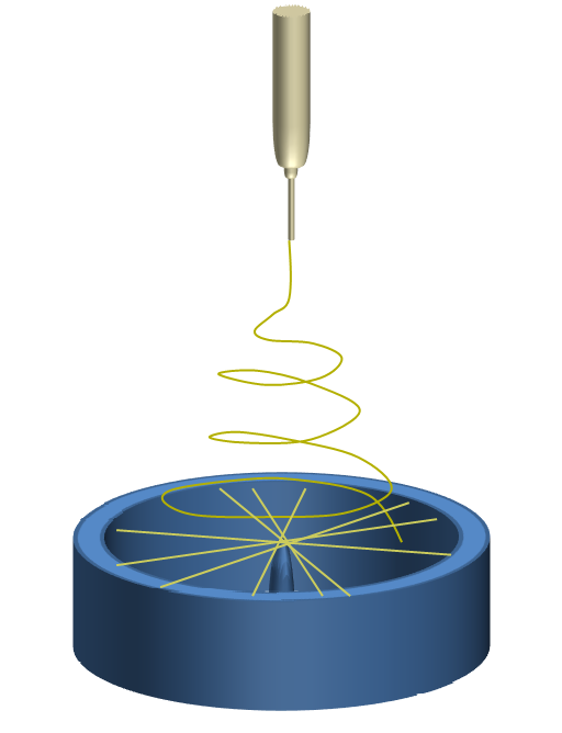
Many variants of this setup have emerged to construct different fiber structures. An array of parallel electrodes has been shown to collect crisscrossing nanofibers at the center [Li et al 2004]. Two sharp edges arranged along a line with a gap in is able to facilitate the construction of nanofiber bundle [Teo and Ramakrishna 2005]. Two sharp edges arranged with the length in parallel was able to collect a thicker aligned fiber mesh [Secasanu et al 2009]. By having a sharp vertical pin placed in the middle of conductive cylinder, a thin circular fibrous membrane with fiber radiating from the center of the pin towards the edges on the cylinder has been constructed [Xie et al 2010].
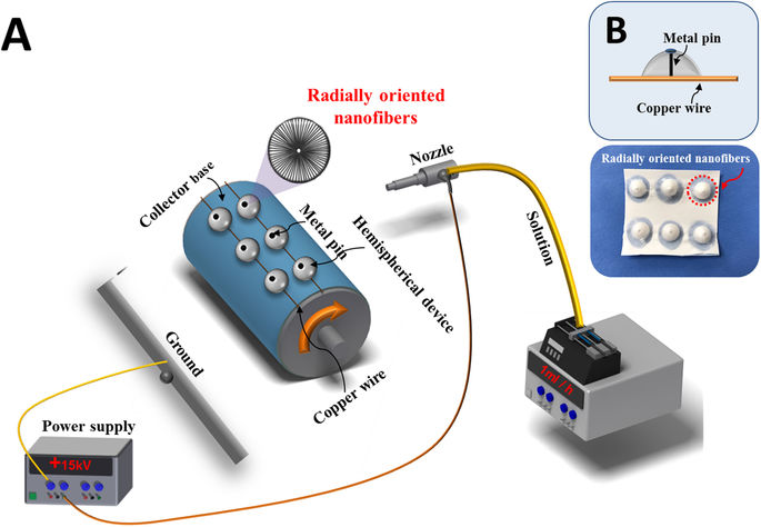
Instead of having a vertical pin in the middle of a conductive cylinder, Kim et al (2018) used a non-conducting hemispherical device instead with the conducting pin in the middle and a wire that forms a ring at the base of the hemispherical device. This setup encourages the formation of a three-dimensional (3D) scaffold with electrospun fibers radiating from the center to the circular wire at the base. Due to the fiber organization, this scaffold was found to exhibit a transparency similar to native cornea in the visible wavelength when wetted in PBS.
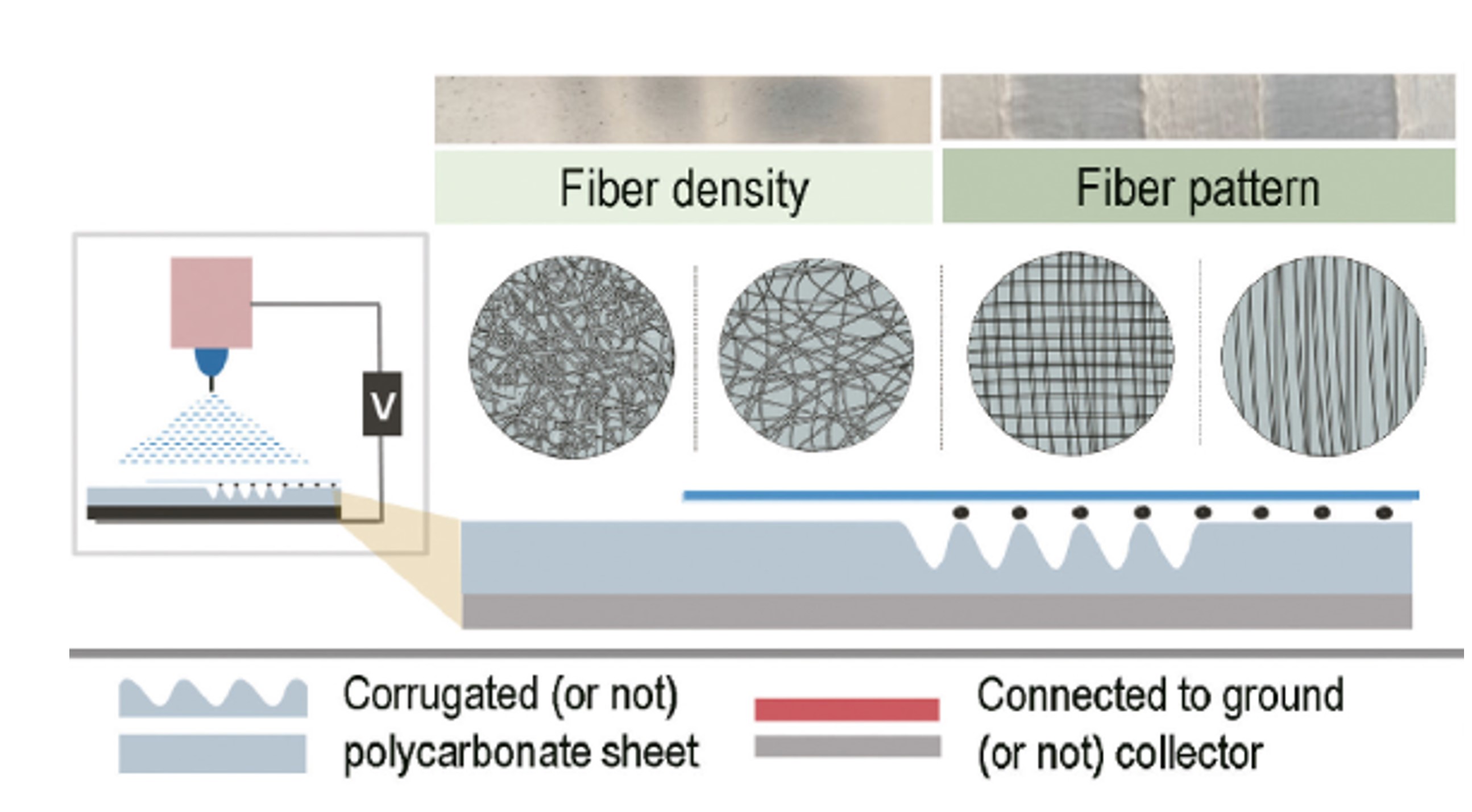
Electrospinning jet is sensitive to small differences in the electric field profile. In a parallel electrode setup, there is competition between fibers depositing on the electrode and across the electrode. Kim et al (2022) showed that this competition due to the electric field profile may be harnessed to form patterned fibers. In their setup, thin wires were used with either flat or corrugated substrate to create the desired electrical field profile. When ungrounded thin copper wires are placed in parallel on a flat substrate and a cellophane membrane placed on top of the copper wires, the fibers are deposited in alignment with the thin wires. However, if the substrate is corrugated and the copper wires are placed along the crest of the corrugation, and similarly, a cellophane membrane is placed on top of the copper, the fibers are deposited in a cross alignment manner, forming square grids. While the copper wire encourages fibers to deposit along its length, the air space between the crest of the corrugated substrate forms a parallel electrode system and this encourages some fibers to cut across the wire.
Unfortunately, there are many limitations to this method. Generating a thick mat of aligned nanofibers is not possible. As the amount of nanofibers deposited at the air gap increases, the air gap disappears and the deposition of the nanofibers becomes disordered [Canejo J P et al 2013]. Researchers have tried to overcome the thickness limitation of this method by concurrently transferring the fibers onto another substrate. Another disadvantage of this method is that the productivity is very poor and there is a lot of wastage due to fibers depositing preferentially on the electrodes instead of spanning across the gap with the mass of aligned nanofibers ranging from 9 to 20% of all electrospun nanofibers [Jalili et al 2006]. This is likely to limit its use in industry where large volume production is essential.
Alternating charged pair electrodes collector
To enable the parallel electrodes collector setup to collect fibers over a larger distance and to form thicker membrane, additional attractive and guided forces through alternate application of opposing charges on the electrodes collector has been tested. With two electrodes collector, an opposing charge is applied to one electrode while the other electrode is neutral. This causes the electrospinning jet to preferentially deposit on the first electrode. The charge is then switched to the other electrode which causes the electrospinning jet to bridge the gap to that electrode. Alternate switching between the charged electrodes will direct fiber deposition accordingly.
This was first demonstrated by Ishii et al (2008) by electrospinning poly[2-methoxy-5-(2'-ethyl-hexyloxy)-1,4-phenylenevinylene](MEH-PPV)/poly(ethylene oxide) (PEO) fibers over 50 mm gap. The fiber diameter was found to reduce from 1350 nm to 531 nm when the gap increases from 5 mm to 50 mm. Such diameter reduction is likely to be caused by stretching of the fibers across the gap. They were also able to control the number of fibers spanning the gap by the number of electrode-voltage switching.
Expansion of this method was carried out by Jose et al (2012) to include different electrodes collector shape for construction of aligned tubes and fiber bundle. They were able to collect fibroin/polyethylene oxide fibrous sheet across a 10 cm gap and showed that the region of highest alignment is at the center of the gap with region of more dense and random fiber organization towards either end close to the electrodes. Examination of the fiber orientation showed 82% of the fibers aligning within 5° of the reference direction while aligned fibers collected using a rotating mandrel yield 22%. This showed the superior fiber aligning ability of this method compared to conventional rotating mandrel method.
Multiple electrodes
The parallel electrodes collector has shown to be very effective in collecting highly aligned fibers. To further improve fiber alignment and density of the collected fibers, steering electrodes have been used together with the parallel electrodes collector. Having the steering electrodes to apply an electric field that confines the path of the electrospinning jet along the plane perpendicular to the parallel electrodes (across the gap) have been shown to improve fiber alignment [Acharya et al 2008].
Using a multiple electrodes system, Shao et al (2021) demonstrated the use of a pair focusing electrodes and parallel electrodes collector to produce highly aligned polyacrylonitrile (PAN) fibers. In their setup, an insulating PTFE Vee-shield was used as the focusing electrodes. As a focusing electrode, the Vee-shield with a slit at the bottom confines the electric potential between the needle and the collector such that it runs parallel to the slit. This causes the electrospinning jet to oscillate along the opening at the bottom of the Vee-shield. To further encourage the electrospinning jet to oscillate along the length of the opening, a cellulose tape covers the length of the grounded electrode at the bottom of the slit such that only the ends of the grounded electrode are exposed. As the cellulose tape masks the middle portion of the grounded electrode, the collector effectively functions as a parallel electrode collector. Therefore, with both focusing electrodes and the parallel electrode collector, highly aligned polyacrylonitrile (PAN) fibers were collected.
Delayed fiber deposition
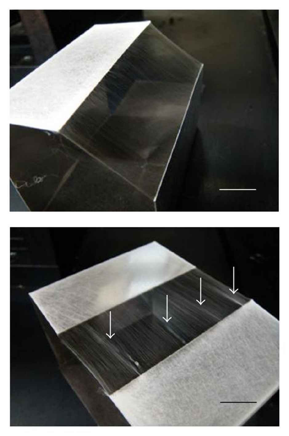
Although fiber alignment in parallel electrodes setup is generally good, modifications to the setup to delay the deposition of fiber across the spacing to the parallel electrodes may further improve the fiber alignment. Park et al [2011] demonstrated that parallel electrodes that were arranged with an inclined spacing was able to give rise to better aligned fibers compared with parallel electrodes arranged in the same level. While the paper did not explain the reason why better aligned fibers were obtained, this may be due to the delayed deposition of the other end of the fiber to the lower electrode. In a typical setup where the parallel electrodes are placed at the same level, both ends of the fibers are deposited on the electrodes almost simultaneously and incoming fibers kept piling on top of preceding deposited fibers. This does not allow the deposited fibers adequate time to align itself across the spacing. As shown in the figure below, fibers collected in parallel electrodes at the same level showed sign of bundling as indicated by the arrow. This may be due to collision between adjacent fibers trying to align across the space. In parallel electrodes arrangement where there is a delay in fiber deposition, this slight delay may give more time for the fibers to arrange in alignment. Thus no sign of fiber bundling was observed in the figure below.
Haseeb B [2011] used a triple electrode setup consisting of three rods arranged in parallel with the outer rods were given a negative charge while the inner rod was given a positive charge which was the same polarity of the electrospinning solution. Using this setup, he was able to encourage the fiber to deposit across central rod with its ends adhered to the outer rods. It was reported that a thick layer of aligned fibers can be collected although there will be a significant amount of fiber wastage as non-aligned fibers tend to collect on the negative electrodes. In a typical parallel electrodes setup, a buildup of fibers will cause a deterioration of fiber alignment due to the accumulation of like residual charges and the reduction in the influence of the parallel electrodes. This condition may be reduced using this setup as the central positive rod applied a repulsive force at the mid-span of the fiber giving more time for the ends of the fiber to find the negative outer electrodes and to take-in the slack fiber span in between. However, more studies will be required to determine whether a three parallel electrodes setup is better than a dual parallel electrodes setup.
Incorporation of magnetic field
Researchers have attempted to use magnetic field to control the electrospinning jet since it carries electrical charges. Orr et al (2015) used a pair of ceramic magnets together with copper electrodes to collected aligned fibers using the parallel electrodes collector arrangement. In general, to achieve good fiber alignment, the distance between the parallel electrodes is generally short (about 2 to 4 cm). However, by having a copper electrode at the edge of the ceramic magnet and placed in parallel with another set of copper electrode and ceramic magnet, Orr et al (2015) was able to get aligned fibers across a gap of 10 cm. However, it is not apparent how the presence of the ceramic magnet facilitated in the bridging of the fibers across such a large gap.
Published date: 12 August 2012
Last updated: 27 December 2022
▼ Reference
-
Acharya M, Arumugam G K, Heiden P A. Dual Electric Field Induced Alignment of Electrospun Nanofibers. Macromol. Mater. Eng. 2008; 293: 666
-
Beachley V, Wen X. Effect of electrospinning parameters on the nanofiber diameter and length. Mater. Sci. and Engin. C. 2009; 29: 663.
Open Access
-
Canejo J P, Godinho M H. Cellulose Perversions. Materials 2013; 6: 1377.
Open Access
-
Formhals Anton. Method and apparatus for spinning. US3260962A. 1939.
Open Access
-
Haseeb B. Controlled deposition and alignment of electrospun PMMA-g-PDMS nanofibers by novel electrospinning setups. MSc Thesis. KTC Chemical Science and Engineering 2011.
Open Access
-
Ishii Y, Sakai H and Murata H (2008) A new electrospinning method to control the number and a diameter of uniaxially aligned polymer fibers. Mater. Lett. 62 pp. 3370
-
Jalili R, Morshed M, Ravandi S A H. Fundamental Parameters Affecting Electrospinning of PAN Nanofibers as Uniaxially Aligned Fibers. J Appl Polym Sci 2006; 101: 4350.
-
Jose R R, Elia R, Firpo M A, Kaplan D L, Peattie R A. Seamless, axially aligned, fiber tubes, meshes, microbundles and gradient biomaterial constructs. J Mater Sci: Mater Med 2012; 23: 2679.
-
Kim J I, Kim J Y, Park C H. Fabrication of transparent hemispherical 3D nanofibrous scaffolds with radially aligned patterns via a novel electrospinning method. Scientific Reports 2018; 8: 3424.
Open Access
-
Kim J H, Lee J H, Kim J Y, Kim S S. Synthesis of Aligned TiO2 Nanofibers Using Electrospinning. Appl. Sci. 2018; 8: 309
Open Access
-
Li D,Wang Y, Xia Y (2003) Electrospinning of polymeric and ceramic nanofibers as uniaxially aligned arrays. Nano Lett. 3 pp.1167
-
Li D, Wang Y, Xia Y (2004) Electrospinning nanofibers as uniaxially aligned arrays and layer-by-layer stacked films. Adv. Mater. 16 pp.361
-
Liu L, Dzenis Y A. Analysis of the effects of the residual charge and gap size on electrospun nanofiber alignment in a gap method. Nanotechnology 2008; 19: 355307.
-
Orr S B, Chainani A, Hippensteel K J, Kishan A, Gilchrist C, Garrigues N W, Ruch D S, Guilak F, Little D. Aligned multilayered electrospun scaffolds for rotator cuff tendon tissue engineering. Acta Biomater. 2015 Article in press
-
Park S H, Wong J W, Shin J H, Yang D Y. Quantitatively Controlled Fabrication of Uniaxially Aligned Nanofibrous Scaffold for Cell Adhesion. Journal of Nanomaterials 2011; 2011: 201969.
Open Access
-
Pokorny M, Niedoba K, Velebny V (2010) Transversal electrostatic strength of patterned collector affecting alignment of electrospun nanofibers. Appl. Phys. Lett. 96, 193111
Open Access
-
Shao S, Ma T, Fernando G F. Electro-spinning of highly-aligned polyacrylonitrile nano-fibres with continuous spooling. Sci Rep 2021; 11: 21713.
Open Access
-
Secasanu V P, Giardina C K, Wang Y (2009) A novel electrospinning target to improve the yield of uniaxially aligned fibers. Biotechnol Prog. 25(4) pp. 1169.
Open Access
-
W E Teo and S Ramakrishna. (2005) Electrospun fibre bundle made of aligned nanofibres over two fixed points. Nanotechnology vol. 16 pg.1878 - 1884.
-
Xie J, MacEwan M R, Ray W Z, Liu Km Suewe D Y, Xia Y. Radially Aligned, Electrospun Nanofibers as Dural Substitutes for Wound Closure and Tissue Regeneration Applications. ACS Nano 2010; 28: 5027.
Open Access
-
Yan H, Liu L, Zhang Z (2009) Alignment of electrospun nanofibers using dielectric materials. Appl. Phys. Lett. 95, 143114.
Open Access
-
Yusuf Y, Ula N M, Jahidah K, Kusumasari E M, Triyana K, Sosiati H, Harsojo. Study of parallel oriented electrospun polyvinyl alcohol (PVA) nanofibers using modified electrospinning method. AIP Conference Proceedings 2016; 1725: 020104. Open Access
▲ Close list