▼ Reference
- Buttafoco L, Kolkman N G, Engbers-Buijtenhuijs P, Poot A A, Dijkstra P J, Vermes I, Feijen J (2006) Electrospinning of collagen and elastin for tissue engineering applications. Biomaterials 27 pp. 724
- Deitzel J M, Kleinmeyer J D, Hirvonen J K, Tan N C B (2001) Controlled deposition of electrospun poly(ethylene oxide) fibers. Polymer 42 pp. 8163
- Huang S H, Chien T C, Hung K Y, Chung Y C. Selective Deposition of Electrospun Alginate-based Nanofibers on cell-repelling hydrogel surfaces for cell-based microarray. 14th International Conference on Miniaturized Systems for Chemistry and Life Sciences 3-7 October 2010, Groningen, The Netherlands. Open Access
- Kim G H (2006) Electrospinning process using field-controllable electrodes. J. Polym. Sci. B 44 pp. 1426
- Kim G, Cho Y S, Kim W D (2006) Stability analysis for multi-jets electrospinning process modified with a cylindrical electrode Eur. Polym. J. 42 pp. 2031
- Kim G H, Han H, Park J H, Kim W D (2007) An Applicable Electrospinning Process for Fabricating a Mechanically Improved Nanofiber Mat. POLYM. ENG. SCI., 47 pp.707-712,
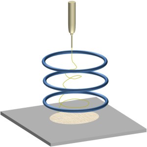
- Lee J S, Ramos-Sebastian A, Yu C, Kim S H. A multi-focused electrospinning system with optimized multi-ring electrode arrays for the wasteless parallel fabrication of centimeter-scale 2D multilayer electrospun structures. Materials Today Advances 2025; 25: 100563. https://www.sciencedirect.com/science/article/pii/S2590049825000086 Open Access.
- Santos J P, Fernandez M J, Fontecha J L, Matatagui D, Sayago I, Horrillo M C, Gracia I. Nanocrystalline Tin Oxide Nanofibers Deposited by a Novel Focused Electrospinning Method. Application to the Detection of TATP Precursors. Sensors 2014; 14: 24231. Open Access
- Stankus J J, Guan J, Wagner W R (2004) Fabrication of biodegradable elastomeric scaffolds with sub-micron morphologies. J. Biomed. Mater. Res. A 70 pp. 603
- Ying Y, Zhidong J, Zhicheng G. Controlled deposition of electrospun poly (ethylene oxide) fibers via insulators. Proceedings of the 15th IEEE International Conference on Dielectric Liquids (ICDL '05), pp. 457-460, Coimbra, Portugal, July 2005.
▼ Credit and Acknowledgement
Author
Wee-Eong TEO View profile
Email: weeeong@yahoo.com
 ElectrospinTech