Self-organization of the spacing between electrospinning jets
High volume output
Cons:
Very high voltage input required
Difficult to maintain consistent solution concentration and viscosity.
Potentially less uniform fiber diameter compared to the orifice technique.
The difference between this and the earlier concept is that there is no physical structures (points or edges) to facilitate charge concentration. Without any preferential location for the initiation of the electrospinning jet, the distribution of the electrospinning jets is dependent on their self-organization and localized charge concentration on the electrified surface or solution. A higher voltage will increase the number of electrospinning jets as the number of localized areas with charges exceeding the critical voltage increases. Conversely, a reduced voltage will decrease the number of electrospinning jets.
In multi-nozzles electrospinning, influence between the electrospinning jets restricts the proximity at which the nozzles can be placed to one another. Similarly for free surface electrospinning, beyond an optimum voltage, further increase may have a negative impact in the electrospinning process as a result of greater jet-to-jet interactions. Above optimum voltage, jet-to-jet interaction will cause a compression in the electrospinning jet cone leading to poor jet stability and reducing the solution flow rate per jet or the number of stable jets. At the onset of jet cone compression, the solution flow rate per jet decreases. When the compression is severe enough to reduce the number of stable jets, the flow rate per jet will increase which may lead to poorer quality fiber such as larger diameter [Roman et al 2013]. However, in either case, the fiber output may be the same or lower with above optimum voltage.
A potential disadvantage of free-surface electrospinning versus needle-based electrospinning is the jet stability and consistency. With a needle-based electrospinning, the base of the Taylor cone has a consistent diameter which is the orifice diameter of the needle. For free-surface electrospinning, the diameter of the Taylor cone base is not confined and may vary from jet to jet. This will result in greater spread of fiber diameter and lesser fiber quality [Vahtrus et al 2015]. However, the benefit of having a much higher electrospinning output using free surface electrospinning may outweigh a slight drop in quality.
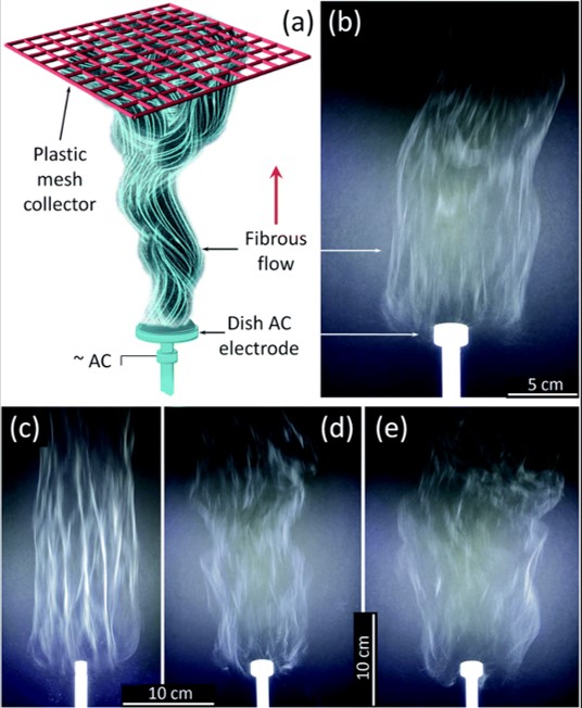
The speed at which charge accumulated on the solution to overcome surface tension and the evolution of fiber jet is very rapid even with free surface electrospinning. Nealy et al (2020) was able to use an alternating current (AC) on a free surface electrospinning setup. For free surface electrospinning a solution of titanium(IV) n-butoxide (Ti(OBu)4)/ polyvinylpyrrolidone (PVP), an alternating current (AC)-voltages up to 40 kV rms at 60 Hz was used. The polymer solution was fed into a shallow dish-like electrode where the AC high voltage was applied. The collector was a PTFE plastic mesh placed about 50 cm above the electrode. Dish-like electrodes with diameters from 10 to 25 mm were tested. With smaller diameter electrodes, an increase of fiber bundling was observed which is not desirable. The feed-rate of the solution was adjusted to support a stable generation of fibers. Assuming the precursor fibers were converted to TiO2, the production rate of TiO2 nanofiber from one electrode is about 5.2 gh-1. The same setup has also been used to produce zirconium titanate nanofibers [Stanishevsky et al 2023].
(a) AFES experiment schematics and photos of the flows of precursor fibers with x1.5 TiO2/polymer yield mass ratio generated (mass of TiO2 generated per unit mass of polymer carrier) on (b) 25 mm and (c) 12.5 mm diameter electrode at 29.5 kV rms AC voltage; and with (d) x0.5 and (e) x2.5 TiO2/Polymer yield mass ratio generated using 25 mm diameter electrode at the same AC voltage [Nealy et al 2020].
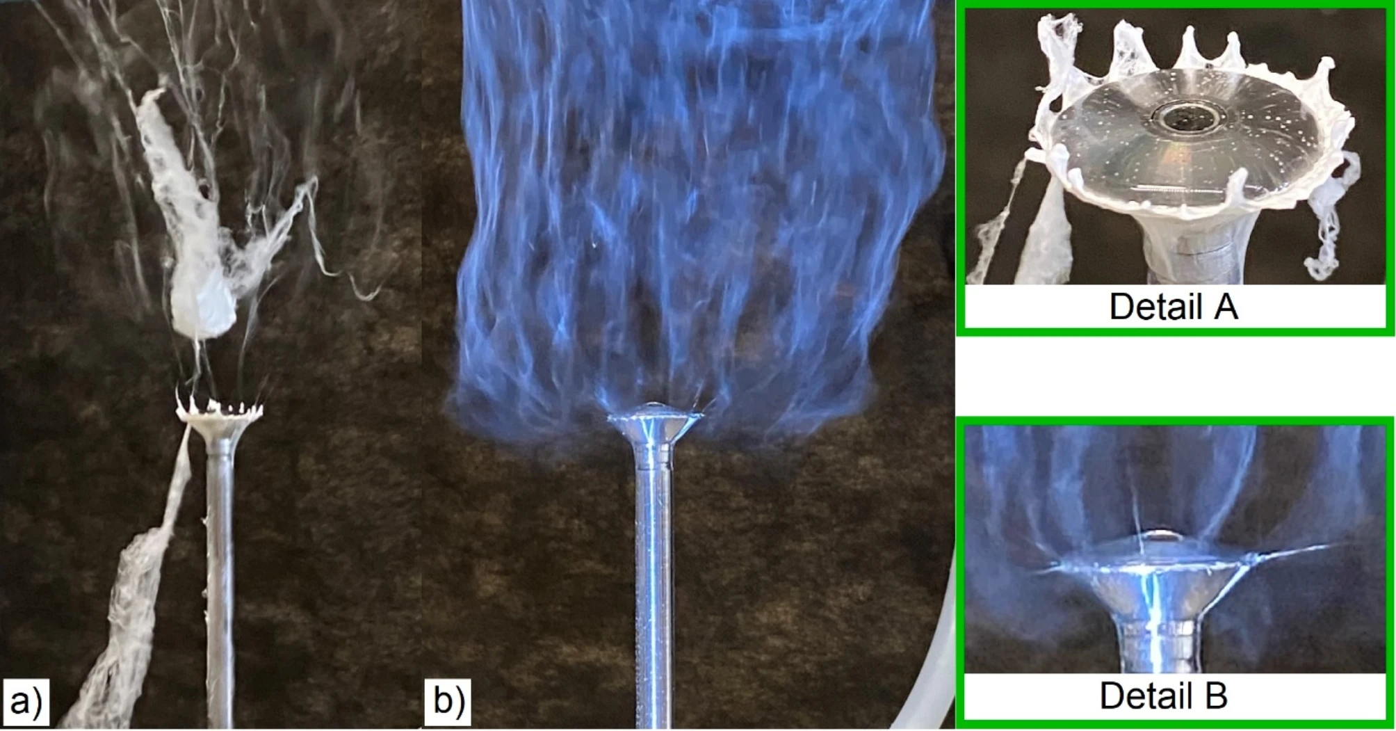
Batka et al (2024) used a weir electrode design for the dispensing of solution in an alternating current (AC) electrospinning. The weir design was in the form of a shallow cone with the solution dispensed from the center and onto the surface of the cone and overflowing down its edge. Their study showed that a rectangular waveform of the electrical signal has higher productivity than a sine waveform in particular at higher voltage. This is probably due to faster attainment of the critical voltage compared to the sine waveform. However, the rapid change in polarity of the rectangular waveform requires a current peak which makes it less safe. Therefore a pseudo-sine waveform with an extended plateau at the critical voltage was used.
The AC-electrospinning proces; (a) unstable spinning, (b) stable spinning [Batka et al 2024].
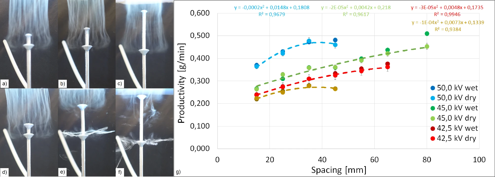
Frequency of the AC input impacts the output quality of the electrospun fibers. Above an optimum frequency of 70 Hz, more residual solvents were found on the sample probably due to the difficulty in forming Taylor cones as a result of the fast polarity switching. At optimum frequency of 70 Hz and voltage of 50 kV, a production rate of 0.45 g/min was achieved. Batka et al (2024) demonstrated the stacking of the weir electrode stage to increase the production rate of the nanofibers. As with electrospinning with multiple needles, the electric field between the stages has an effect on the electric field. A greater distance between the stages reduces the electric field interference hence increasing the productivity of the setup. However, at spacing larger than 45 mm, the electric field strength between the lower stage and the collector was too weak for electrospinning.
(a) 1st stg. 14 mm 2nd stg. 26 mm pitch 15 mm, a) 1st stg. 14 mm 2nd stg. 26 mm pitch 65 mm, a) 1st tg. 14 mm 2nd stg. 26 mm pitch 80 mm, (d) identical diameters pitch 15 mm, (e) identical diameters pitch 65 mm, (f) identical diameters pitch 80 mm, (g) productivity dependence on the pitch [Batka et al 2024].
Reservoir
In the simplest setup, a reservoir of solution with a collector above is sufficient to collect fibers if the solution is able to gain sufficient charge. However, the amount of voltage required to charge the solution sufficiently for electrospinning to occur is very high and may not be practical for all solutions. Instead of having a reservoir of solution, a variation is to apply a thin layer of polymer solution on a flat surface [Roman et al 2013]. With this simple modification, the position of the solution plate facing the collector need not be restricted to bottom up.
Electrospin free surface reservoir. Click image to enlarge.
Drum
A charged drum where its surface is constantly replenished with a layer of solution is more effective in transferring charges to the surface and hence improve the fiber spinning process. The electrospinning jets erupting from the surface of the drum will be able to self-organize but they will be cut off when the side of the drum dips into the solution reservoir [Niu et al 2012]. Another difficulty in free surface electrospinning is when the solution viscosity increases. With a rotating drum to dispense the electrospinning solution, the number of electrospinning jet initiation from the surface reduces as the viscosity increases until only jets at the edges remains. This is due to the greater electric field strength from the edges of the drum compared to the flat center of the drum. As the viscosity increases, greater field strength is needed to cause corona discharge and surface perturbation for jet initiation. However, the applied voltage cannot increase indefinitely as dielectric breakdown of the air and arcing would occur between the collector and the electrode [McCarthy et al 2019] .
In a modification of this setup, instead of replenishing the solution on the surface of the drum using a solution reservoir, doplets of solution may be dispatched onto the surface of the charged drum or roller. As each droplet hit the charged surface, an electrospinning jet would erupt off the surface [Tang et al 2010].
Uhljar et al (2022) did a comparison of the ciprofloxacin (CIP)-loaded polyvinylpyrrolidone (PVP) electrospun fibers using a drum surface electrospinning setup and single nozzle electrospinning setup. At the same concentration, the single nozzle electrospun fibers have an average diameter of 323 nm while the drum surface electrospun fibers have an average diameter of 1167 nm. The coefficient of variation for the drum surface electrospun fibers was also much larger than that of single nozzle electrospun fibers. However, due to larger spread of fibers emitting from the drum surface, the uniformity of fiber coverage on the collector surface was better for the drum surface electrospun fibers.
Electrospinning using a drum partially submerged in solution reservoir. Click image to enlarge.
Drum Youtube Video
Ball Electrospinning
To further increase the solution spinning surface area, an array of balls is arranged on a solution reservoir. Electrospinning jets erupting from the surface of the balls are similar to that of a drum in terms of their ability to self organize. However, as a spherical ball has greater surface area compared to a cylindrical drum, more electrospinning jets should erupt from the spinning surface. Comparison of the average fibre production rate between single needle electrospinning and single ball electrospinning give output of 0.37 mg/min and 32 mg/min respectively. Using 6 wt% polyacrylonitrile solution, the average number of jets from a ball was 24 and with a higher concentration of 8 wt%, the number increases to 38 [Willemse A C 2013]. This setup is used commercially by Stellenbosch Nanofiber Company to fabricate their nanofibrous product.
Ball electrospinning with an array of balls partially submerged in solution reservoir. Click image to enlarge.
Ball electrospinning Youtube Video
In a setup that is a hybrid of ball electrospinning and nozzle electrospinning, Zhang et al (2018) created a bead-type nozzle, where is a ball inside the needle tip. This design was adapted from traditional ballpoint pen where the solution flows through the gap between the wall of the nozzle and the sphere. Using this setup, when the voltage increases, the number of electrospinning jets increases accordingly. This has the advantage of optimizing the number of electrospinning jets for the given voltage. The estimated production rate using this setup is 10 to 12 times faster than conventional needle tip electrospinning.
Published date: 04 Aug 2012
Last updated: 06 May 2025
Batka O, Skrivanek J, Holec P, Beran J, Valtera J, Martin Bilek M. Methods for increasing productivity of AC-electrospinning using weir-electrode. Sci Rep 2024; 14: 24012.
https://www.nature.com/articles/s41598-024-75946-5 Open Access
McCarty R J, Giapis K P. An Adaptable Device for Scalable Electrospinning of Low- and High-Viscosity Solutions. Instruments 2019; 3: 37.
Open Access
Nealy S L, Severino C, Brayer W A, Stanishevsky A. Nanofibrous TiO2 produced using alternating field electrospinning of titanium alkoxide precursors: crystallization and phase development. RSC Adv., 2020; 10: 6840.
Open Access
Niu H, Wang X, Lin T (2012) Upward Needleless Electrospinning of Nanofibers. JEFF 2012 pp. 17.
Open Access
Roman M P, Thoppey N M, Gorga R E, Bochinski J R, Clarke L I. Maximizing Spontaneous Jet Density and Nanofiber Quality in Unconfined Electrospinning: The Role of Interjet Interactions. Macromolecules 2013; 46: 7352.
Stanishevsky A, Yager R, Nealy, S Severino C, Maniukiewicz W. High throughput fabrication of zirconium titanate nanofibers by using alternating field electrospinning. Materials Letters 2023; 330: 133318.
Open Access
Tang S, Zeng Y, Wang X (2010) Splashing needleless electrospinning of nanofibers. Polymer Engineering and Science, vol. 50, no. 11, pp. 2252-2257.
Uhljar LÉ, Alshweiat A, Katona G, Chung M, Radacsi N, Kókai D, Burián K, Ambrus R. Comparison of Nozzle-Based and Nozzle-Free Electrospinning for Preparation of Fast-Dissolving Nanofibers Loaded with Ciprofloxacin. Pharmaceutics. 2022 Jul 27;14(8):1559.
Open Access
Vahtrus M, Sutka A, Vlassov S, Sutka A, Polyakov B, Saar R, Dorogin L, Lohmus R. Mechanical characterization of TiO2 nanofibers produced by different electrospinning techniques. Materials Characterization 2015; 100: 98.
Willemse A C. Electrospinning Bicomponent Nanofibres for Platinum Ion Extraction from Acidic Solutions. MSc Thesis. Stellenbosch University 2013.
Open Access
Zhang Y, Cheng Z, Han Z, Zhao S, Zhao X, Kang L. Stable multi-jet electrospinning with high throughput using the bead structure nozzle. RSC Adv. 2018; 8: 6069.
Open Access