The mechanical property of a fibrous membrane comes from the arrangement of the fibers. Therefore, when the membrane is made out of helical fibers instead of straight fibers, a change in mechanical properties can be expected. There are also other potential benefits of having helical fibers, Zhao et al (2017) showed that helical fibers are better at trapping oil compared to straight fibers.
Electrospinning jet is known to travel in a chaotic but largely helical motion in flight. Observation of helical nanofibers on a flat plate collector has been reported by several researchers especially when the collector is moving relative to the nozzle tip. Getting individual helical strand of electrospun fibers is as simple as catching the fibers in a slow moving collector. For some, this is considered an artefact due to buckling of the nanofibers upon impacting the collector when the collector speed is insufficient to lay the nanofiber straight [Zheng et al 2012].
Electrospun helical fibers have been reported by various research groups. In some cases, general buckling of the electrospinning jet on the collector was able to yield helical fibers. Yu et al (2008) was able to collect electrospun helical polycaprolactone (PCL) by having a tilted glass slide as collector. Since the deposition of helical fibers were due to the electrospinning jet impacting the surface of the collector, the gradient of tilt and the distance of the collector away from the electrospinning nozzle determine the formation of the helical fibers.
A side-by-side dual orifice nozzle may be used to extrude two different solutions such that a single electrospun fiber is made out of two materials along its length. When there is differences in the shrinkage or expansion property between the materials, the fiber may coil into a helical form. Such an output has been demonstrated by Zhang et al (2009) using high shrinkage polyethylene terephthalate (HSPE) and polytrimethylene terephthalate (PTT) as the bicomponents. Lin et al (2005) showed that using polyacrylonitrile (PAN) and polyurethane (PU) as the two materials in their bi-component system, they were able to construct curly and helically crimped fibers. This behavior has been attributed to differential shrinkage within the fibers which causes one of the components to compress. Increasing the amount of PAN by increasing its flow rate leads to less curly nanofibers while the converse is true when the PU content was increased. Chen et al (2009) showed that very curly nanofibers may work as a nanospring and this may influence the mechanical properties of the resultant mat. Using poly(m-phenylene isophthalamide) (Nomex) and thermoplastic polyurethane (TPU), they found that the net elastic force of the aligned nanospring fibers from side-by-side bicomponent fiber showed a higher elongation, higher toughness and higher modulus than fibers without nanospring. Fibers with and without the nanospring were both side-by-side bicomponent fibers. To obtain aligned fibers without nanospring, the collector was set at a higher rotation speed while aligned fibers with nanospring were collected with lower rotation speed. Wu et al (2018) did a study on the potential for helical fiber formation of three polymers, poly(m-phenylene isophthalamide) (Nomex), polystyrene (PS) and polyacrylonitrile (PAN) with polyurethane (TPU) in side-by-side bicomponent form. Of the three polymers, only Nomex was found to form consistent helical fibers with TPU. Three possible hypothesis was brought forward from their investigation. Nomex has the highest stiffness compared to PS and PAN and the greatest difference in the material stiffness against TPU. In terms of miscibility of the solution with TPU solution, PS solution is completely immiscible with TPU solution, PAN solution is completely miscible while Nomex solution is partially miscible. Partially miscible solutions may facilitated in the bonding between the two polymer components and would have helped in the helical fiber formation. Lastly, Nomex solution was found to exhibit Coulomb force between the solution and the polymer molecule during electrospinning and this generates a longitudinal interfacial stress between the Nomex and TPU solutions to encourage helical structure formation. Such Coulomb forces were not found in other polymer solutions. Instead of using hydrophobic NOMEX with TPU, Wu et al (2018A) showed that helical fibers may also be formed using hydrophilic cellulose acetate (CA) with TPU. To generate helical electrospun CA/TPU bicomponent fibers, LiCl salt must be added to the solution. The presence of LiCl aided in the stiffening of CA such that the stiffness difference between CA and TPU polymer chains are greater. LiCl also increases the conductivity of the solution and the longitudinal interfacial stress between the molecular chain and the solution. However, the experiment also showed that beyond an optimum concentration of LiCl, less helical fibers were formed which was attributed to excessive conductivity that stretched the helical fiber to form a straight fiber.
While it is evident from their studies that not all bicomponent polymer fibers will form helical fibers, more studies will be needed to determine the requirement for helical fiber formation.
Helical bicomponent fibers need not be restricted to side-by-side arrangement. Zhao et al (2017) showed that a core-shield bicomponent electrospun fibers may also form helical fibers. In their study, electrospun polyvinylidene fluoride (PVDF) with a good ductility was utilized as the core and stiffer, porous polystyrene (PS) as the shell. On a stationary collector, helical fibers were formed. A rotating drum collector was used to collect straight fibers.
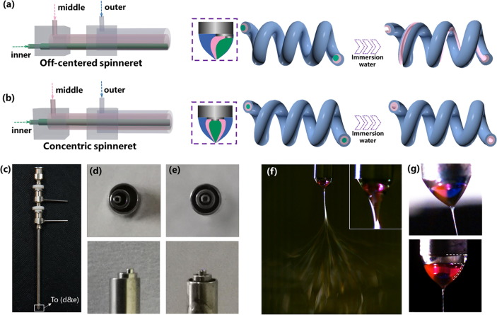
Zhao et al (2021) also showed that helical electrospun fibers may be formed if two materials of dissimilar modulus were used in a triaxial nozzle. Three working components for their setup were cellulose acetate (CA), thermoplastic polyurethane (TPU), and polyvinylpyrrolidone (PVP). CA and TPU were the outer and middle components and PVP was the inner sacrificial component to be removed for the generation of hollow or groove structure. CA and TPU were selected due to their significant difference in modulus which encouraged the formation of helical nanofibers. For the formation of groove structure, the channels of the tri-axial spinneret were off-centered. With the core channel off-set to one side, the water soluble PVP core will be nearer to one side of the fiber. After the fibers were immersed in water, dissolution of the PVP formed a groove along one side of the fiber. To maintain a helical shape of the fiber, the flow rate of the PVP solution core needs to be sufficiently low as higher PVP solution flow rate results in mostly straight fibers. This is probably due to greater core thickness at higher core flow rate which resists bending of the electrospinning jet.
Helical inorganic fibers have been constructed by sintering core-shell fibers with the pure inorganic precursors as the core. Dong et al (2024) demonstrated this using polyvinylpyrrolidone (PVP) as the shell material and precursors of TiO2 and ZrO2 as the core. Polycrystalline TiO2 fibers after sintering and pyrolysis of PVP showed helical structure with excellent flexibility and a high Young's modulus of 54.3 MPa. Similarly, ZrO2 fibers using the same process showed Young's modulus and toughness of 130.5 MPa and 11.9 KJ/m3, respectively. Both TiO2 and ZrO2 produced using the core-shell electrospinning method showed significantly better mechanical properties compared to the conventional blended method. The formation of the helical fiber has been attributed to crack formation on the surface of one side of the initial core-shell fiber during sintering. During electrospinning, stiffness of the core alkoxide sol as it vaporizes led to an uneven shrinkage of the ductile shell due to the constraint from the core-shell interface and the surface of the fiber. This resulted in cracks on the fiber shell, which distribute asymmetrically about the fiber axis and rotate along the change of the curving direction. As the fiber shrinks due to the surface PVP decomposition, the fiber starts to curl towards the side with the crack. With a thinner shell, the uneven shrinkage of the shell from the core-shell interface and its surface was less pronounced and no coiling of the fibers were observed.
Published date: 27 March 2018
Last updated: 10 February 2026
▼ Reference
-
Chen S, Hou H, Hu P, Wendorff J H, Greiner A, Agarwal S. Effect of Different Bicomponent Electrospinning Techniques on the Formation of Polymeric Nanosprings. Macromol. Mater. Eng. 2009; 294: 781.
-
Dong S, Maciejewska B M, Schofield R M, Hawkins N, Siviour C R, Grobert N. Electrospinning Nonspinnable Sols to Ceramic Fibers and Springs. ACS Nano 2024; 18 (21): 13538.
https://pubs.acs.org/doi/full/10.1021/acsnano.3c12659Open Access
-
Lin T, Wang H, Wang X. Self-Crimping Bicomponent Nanofibers Electrospun from Polyacrylonitrile and Elastomeric Polyurethane. Adv. Mater. 2005; 17: 2699.
-
Wu H, Zhao S, Ding W, Han L. Studies of Interfacial Interaction between Polymer Components on Helical Nanofiber Formation via Co-Electrospinning. Polymers 2018; 10(2): 119.
Open Access
-
Wu H, Zhao S, Han L. Fabrication of CA/TPU Helical Nanofibers and its Mechanism Analysis. Nanoscale Research Letters 2018A; 13:104.
Open Access
-
Yu J, Qiu Y, Zha X, Yu M, Yu J, Rafique J, Yin J. Production of aligned helical polymer nanofibers by electrospinning. European Polymer Journal 2008; 44: 2838.
-
Zhang B, Li C, Chang M. Curled Poly(ethylene glycol terephthalate)/Poly(ethylene propanediol terephthalate) Nanofibers Produced by Side-by-side Electrospinning. Polymer Journal 2009; 41: 252.
-
Zhao T, Zheng Y, Zhang X, Teng D, Xu Y, Yongchun Zeng Y. Design of helical groove/hollow nanofibers via tri-fluid electrospinning. Materials & Design 2021; 205: 109705.
Open Access
-
Zhao Y, Miao X, Lin J, Li X, Bian F, Wang J, Zhang X, Yue B. Coiled Plant Tendril Bioinspired Fabrication of Helical Porous Microfibers for Crude Oil Cleanup. Journal of Polymer Science Part B: Polymer Physics 2018; 56: 36.
Open Access
-
Zheng J, Sun B, Long Y Z, Zhang H D, Zhang Z M, Zhang Z H, Han W H, Shao F, Huang J Y.Fabrication of Nanofibers by Low-Voltage Near-Field Electrospinning. Advanced Materials Research 2012; 486: 60.
▲ Close list