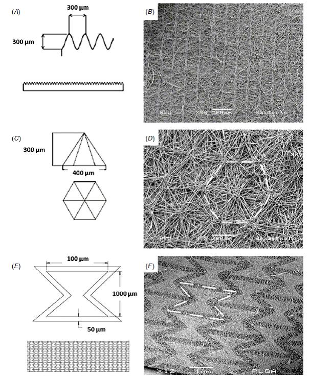
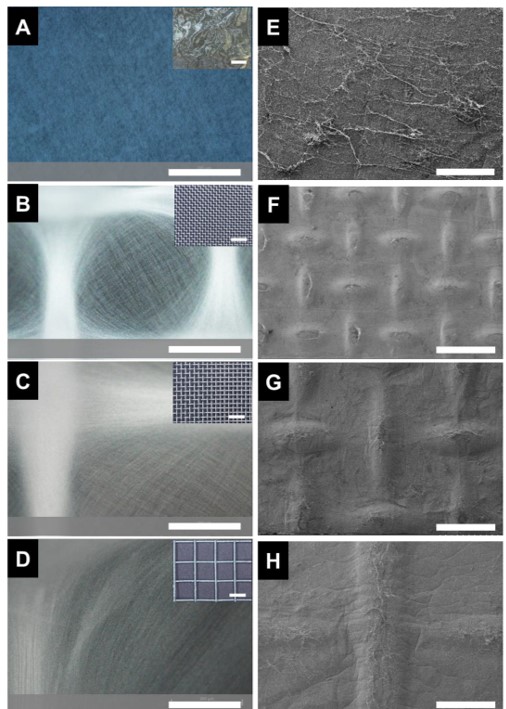
Electrospinning jet has been shown to be sensitive to small differences in the electric field profile. Electrospinning jet using polycaprolactone solution was able to discern conductive lines with widths of 350 µm and spacing of 1.7 mm [Wu et al 2010]. The actual resolution is better than this as an imprint of conductive letters of size 1 mm by 1 mm on an insulating plastic has been made using electrospun fibers [Wu et al 2010]. Conductive collecting substrate with textured surface such as wire mesh or grids has been used to form patterned/textured nanofibrous membrane due to its electric field profile. In a typical square grid substrate, fibers are preferentially deposited along the wire. As the wires forming the grid are narrow, fibers tend to align along the length of the wire. Despite preferential deposition of fibers on the wire, presence of numerous neighbouring wires often diverts the electrospinning jet to the adjacent wire. This resulted in a higher density of fibers which are aligned on the wire than randomly oriented, scattered fibers at the gaps between the wires. Where the distance between the wires get larger, the difference in the density of fibers on the wires and the space between the wires increases [Vaquette et al 2011]. Analysis of the fiber diameter between the fibers deposited on the wire and the space between revealed smaller diameter for the fibers in the space. This has been attributed to greater stretching of the fibers when it spans across ths space[Vaquette et al 2011]. Other forms of patterned substrates have also been used to collect fibers. Grids made out of parallel wires close to one another has been shown to form dense, aligned nanofibers between the wires while a substrate with arrayed pins give rise to membrane made out of radiating nanofibers between the pins [Zhang et al 2008]. More grids variations such as having a pin in the center of a round space formed a pattern where fibers radiates from the central pin to the edges [Vaquette et al 2011]. Liu et al (2018) conducted further studies on the influence of pin arrays on the resultant electrospun fibrous structure. In general, fibers are preferentially deposited on the tips of the needles. When the height of the needles are uniform, deposited fibers form a flat membrane on top of the needles. To create a structure with different elevations, the needle height may be varied. A pyramid shell shape may be constructed by elevating needles in the center of the array. A wave profile may be constructed by alternating the height of rows of needles. A needle array instead of a flat plate collector thus allowed greater variation in the electrospun fiber structure. With increasing flow rate and voltage, the deposition area across the needle arrays decrease.
Ordering of electrospun fibers on a patterned collector is primarily due to the electric field profile between the source and the collector. Titov and Tan (2016) carried out a more detailed investigation of the electric field influence on electrospun fiber patterning. Using computer modelling on the electric field, they found that near the nozzle tip, the electrospinning jet would not experience any difference in the electric field profile between a patterned collector and a smooth plate collector. However, the electric field potential when it gets close to the patterned collector (< 1 mm) showed significant increase in field strength in the horizontal direction. When the mat thickness increases to more than 500 µm, the fiber orientation becomes more disordered. This has been attributed to reduction of space between the struts of the patterned collector as fibers deposited on them and also an increased in residual charges from the deposited fibers which weakens the electric field strength.
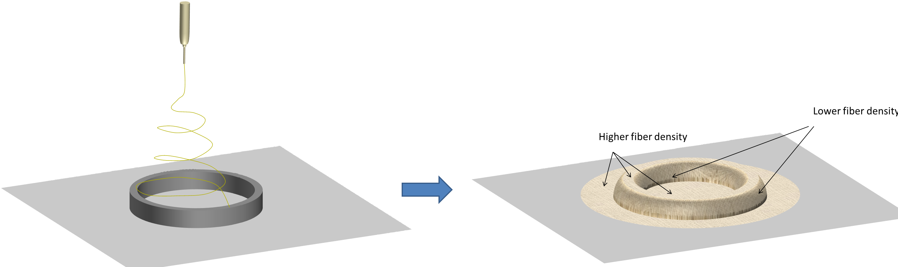
Perhaps the most basic patterned structure comprises of fibrous membrane constructed from a single "cell" template. Typical grid structures are made out of numerous repeating "cells" arranged in an array. A single "cell" is made out of just one elevated unit such as a ring structure. With a ring structure, it elevated part of the ring disrupts an otherwise flat surface both physically and the electrical profile. Electrospinning jet responding to the disruption will deposit the fibers according to the electrical and physical profile. Given that the electrical potential of the ring and the ground is uniform, the electrospinning jet will be attracted to the surfaces that are closer to it. In this case, it will get attracted to the raised area of the ring and the ground location which is at a slight distance away from the corner where the ring touches the ground. This forms a "parallel electrodes collector" configuration where the corner of the ring which touches the ground acts like the gap in the "parallel electrodes collector" configuration. This causes the fibers to lean in parallel from the ground against the wall of the ring forming region of lower fiber density [Ortega et al 2013]. As the height of the ring increases, the fibers get deposited further from the corner. This creates a single membrane with distinct regions of high fiber density and lower fiber density [Ortega et al 2013]. More studies are required to examine the effect of minute differences in electric potential and fiber deposition. With this, membrane with interesting fiber distribution and arrangements may potentially be constructed through a single electrospinning run and tailored for specific applications.
Using a template to create patterned electrospun structures is not restricted to just flat membrane. Hong et al (2009) was able to create electrospun tube with circumferentially aligned fibers and parallel grooves (3.6 µm channel x 3.3 µm ridge x 1 µm depth) running along the inner length of the tube. These grooves are created by depositing the fibers on a rod covered with a poly(dimethylsiloxane) sheet patterned with longitudinally aligned parallel gratings. Circumferential alignment of the electrospun fibers comes from the mechanical rotation of the rod. Brown et al (2014) used melt electrospinning on a dome shaped patterned collector. Long stable jet from melt electrospinning of polycaprolactone lay predominantly on the wire grids and formed a replica of the underlying patterned collector except that it is made out of raised fibers. The end result is a bowl-shaped fibrous structure with regular pores with average pore size of 250 µm. It is easy to envision that such porous structure has the potential for use in bone replacement graft.
To create customized patterned grids for electrospinning patterned nanofibrous membrane, rapid prototyping may be used to create the grids. Since the materials used in rapid prototyping are usually polymer and thus non-conductive, Rogers et al (2014) were able to overcome this by sputter coating a thin layer of gold on the 3D printed grid. Electrospinning poly(D,L-lactide-co-glycolide) (PLGA) over the various custom patterned grid give rise to uneven distribution of fibers over the apex of the ridges and the gap in between. In agreement with the observation by Vaquette et al (2011), the fiber diameter was found to be slightly different between those on the apex of the ridges and the gap in between. With the designs comprising of parallel gaps, the fiber diameter on the apex are larger than those fiber in between the gap. However, with re-entrant honey-comb design, it is the fibers in the gap that has larger fiber diameter [Rogers et al 2014]. More studies are required to investigate the electric field profile effect affects the stretching of the fibers and the fiber diameter.
The mechanical properties of the textured nanofibrous membrane have been reported in some studies. Tear resistance of the textured membrane has shown to be much better than un-textured nanofiber membrane. With "ridges" of adequate thickness, they are able to deflect the crack propagation and therefore resist tearing [Gibson et al 2004]. Between textured nanofiber mesh and randomly oriented nanofiber mesh of polycaprolactone, textured nanofiber mesh showed a higher tensile tangent modulus (62.7 MPa for textured and 44 MPa for randomly oriented mesh) but lower ultimate tensile stress (28.6 MPa for textured and 33.2 MPa for randomly oriented mesh) and ultimate strain (-87.3% for textured and 146.46% for randomly oriented mesh) [Wang et al 2009]. A study by Neve et al (2007) also demonstrated weaker ultimate tensile strength of patterned nanofiber mesh compared to randomly oriented nanofiber mesh. Such weakness may be due to local stress concentration at the intersection between thicker region or nanofibrous ridges on the membrane. The design of the pattern and the wire spacing may also play a part in the stress concentration on the membrane. Yan et al (2013) showed that with a denser wire spacing (wire spacing of 0.381 mm) and smaller diameter wire (0.254 mm diameter), the resultant electrospun polycaprolactone patterned membrane has a higher ultimate tensile strength compared to randomly oriented electrospun membrane. However, with a more open patterned grid (wire spacing 0.864 mm and diameter 0.4 mm), the ultimate tensile strength was lower than randomly oriented nanofiber membrane. Using a square grid mesh with 0.6 mm inter-wire length and 250 micron wire diameter, Caloin et al (2023) found that there was a 2 fold increase in the flexural rigidity in the electrospun nylon-6 fibers collected compared to samples collected on a foil. Increasing inter-wire length with corresponding thicker wire diameter gave decreasing flexural rigidity although still higher than foil collected electrospun fibers. The water contact angle of the electrospun patterned membrane was found to be similar to that of foil collected membrane at about 137 °. Therefore the presence of patterns have less impact on water contact angle with the interfibers distances playing a more significant role.
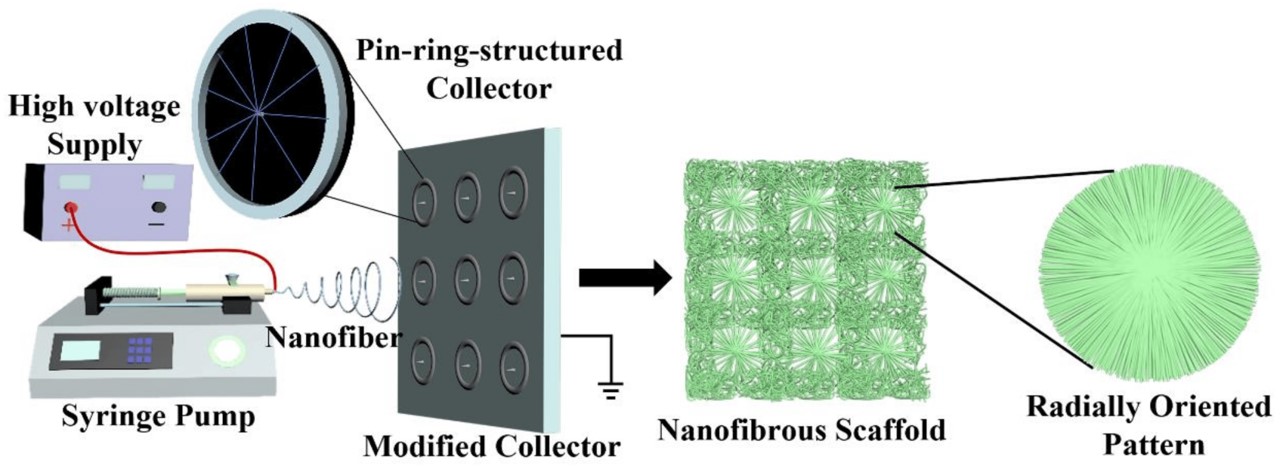
Wang et al (2023) used an array of rings with a pin at the center of each ring to create arrayed radially oriented fibrous patterns on an electrospun membrane using poly(3-hydroxybutyrate-co-3-hydroxyvalerate) (PHBV) as the material. The electrospun PHBV membrane with randomly oriented fibers has a water contact angle of 143° while the membrane with radially oriented fibrous patterns exhibited a lower water contact angle of 126°. However, due to the nonhomogeneous surface of the radially aligned nanofiber scaffold, the water contact angle may vary across its surface. The radially aligned array of nanofibers gave the membrane greater modulus and ultimate tensile strength compared to randomly oriented nanofiber membranes (169 MPa vs 68 MPa and 5 MPa vs 2 MPa respectively). This is probably due to more rapid alignment of the fibers in the direction of the force with the radially oriented fibers.
Patterned nanofibrous mesh has been tested for some applications. Cell culture comparing proliferation of mouse osteoblastic cell between patterned/textured nanofiber and randomly oriented nanofiber showed faster proliferation on the textured nanofiber membrane. However, initial cell adhesion is better on randomly oriented nanofiber membrane [Wang et al 2009]. Neves et al (2007) has observed that osteoblastic cells showed preferential adhesion to the regions of randomly oriented nanofibers and this may explain the lower cell numbers recorded by Wang et al (2009) on day 1 for patterned nanofiber mesh compared to unpatterned, randomly oriented nanofiber membrane.
With a radially aligned array of nanofibers PHBV scaffold, human-adipose-derived mesenchymal stem cells (HAMSCs) were found to exhibit greater proliferation compared to cells cultured on randomly oriented nanofibers scaffold [Wang et al 2023]. On randomly aligned nanofibers scaffold, the spread of the cells were chaotic in contrast with the cells spreading along the fiber alignment of the radially aligned fiber pattern. Cells are known to migrate along the direction of underlying fiber orientation and this may have facilitated their migration and freeing up more space for cell proliferation.
Patterned nanofibrous membrane was also shown to have varying pore sizes between the fibers deposited on the wire and the space between. Larger pore size in the space between has been shown to faciliated fibroblast migration into the depth of the membrane compared to the thicker segments where the cells tend to remain on its surface [Vaquette et al 2011]. The favorable tear resistance characteristic of the membrane makes it a potential candidate for air filtration. For this application, Gibson et al [2004] found that textured membrane has no effect on air flow resistance and particle filtration. Textured indium tin oxide nanofiber membrane has also been fabricated showing excellent optical transparency and electrical conductivity [Munir et al 2008].
Textured electrospun membranes exhibited varying surface roughness depending on the pattern. Pentogonal grid profile membrane (4.16 µm) has the highest roughness value compared to smooth surface electrospun membrane (0.814 µm) and tetragonal grid profile electrospun fibers (2.29 µm). Saadatmand et al (2019) tested the effect of textured electrospun membrane on the release rate of cetirizine in Nylon 6 fibers. Electrospun Nylon 6 fibers were deposited on smooth surface substrate, pentagonal grids and tetragonal grids. From their study, they found that drug release from membrane with pentagonal profiling has the fastest release rate and followed a first order release model where the release rate is concentration dependent. Both smooth surface and tetragonal profile membrane followed a Higuchi model where the release rate is slower. In the medical setting, specialized gowns and fabrics are used for protection against radiation especially during the use of X-ray. Kim et al (2024) examined the influence of different electrospun patterned nanofibers membranes on its shielding performance. To give the membrane its shielding property, tungsten particles were dispersed in polyurethane (PU) solution before electrospinning. Honeycomb pattern membrane (P1) showed the best shielding where the tungsten particles are better distributed. Other patterns showed varying degrees of fiber and particle aggregation resulting in lower shielding performance. Comparing 0.3 mm fabric made of the honeycomb membrane with 0.25 mn lead, shielding from lead is better at the low incident energy region but at higher energy regions of 35 keV and above, the shielding performance was closer.
Published date: 03 February 2014
Last updated: 11 June 2024
▼ Reference
-
Ayaz H G S. Textile-Templated Anisotropic Electrospun Scaffolds for Cardiac Tissue Engineering. PhD Thesis 2012. Drexel University.
-
Brown T D, Edin F, Detta N, Skelton A D, Hutmacher D W, Dalton P D. Melt electrospinning of poly(ε-caprolactone) scaffolds: Phenomenological observations associated with collection and direct writing. Materials Science and Engineering C 2014 Ahead of print
-
Caloian I, Trapp J, Williams MW, Kim RA, Moustafa ME, Stwodah EH, Tang C. Direct Fabrication of Functional Shapes on 3D Surfaces Using Electrospinning. Polymers 2023; 15(3):533.
Open Access
-
Gibson P, Schreuder-Gibson H. Patterned Electrospray Fiber Structures. INJ Summer 2004; 37.
Open Access
-
Kim S-C. Study on the Changes in Shielding Performance Based on Electrospinning Pattern Shapes in the Manufacturing Process of Polymer-Metal Composite Radiation Shielding Materials. Coatings. 2023; 13(6):1028.
Open Access
-
Liu Y, Liu R, Wang X, Jiang J, Li W, Liu J, Guo S, Zheng G. Electrospun Three-Dimensional Nanofibrous Structure via Probe Arrays Inducing. Micromachines 2018; 9: 427.
Open Access
-
Munir M M, Widiyandari H, Iskandar F, Okuyama K. Patterned indium tin oxide nanofiber films and their electrical and optical performance. Nanotechnology 2008; 19: 375601.
-
Neve N M, Campos R, Pedro A, Cunha J, Macedo F, Reis R L. Patterning of polymer nanofiber meshes by electrospinning for biomedical applications. Int. J. Nanomed. 2007; 2: 433.
-
Ortega I, Ryan A J, Deshpande P, MacNeil S, Claeyssens F. Combined microfabrication and electrospinning to produce 3-D architectures for corneal repair. Acta Biomaterialia 2013; 9: 5511.
-
Rogers C M, Morris G E, Gould T W A, Bail R, Toumpaniari S, Harrington H, Dixon J E, Shakesheff K M, Segal J, Rose F R A. A novel technique for the production of electrospun scaffolds with tailored three-dimensional micro-patterns employing additive manufacturing. Biofabrication 2014; 6: 035003.
Open Access
-
Saadatmand M M, Yazdanshenas M E, Khajav R, Mighani F, Toliyat T. Patterning the surface roughness of a nano fibrous scaffold for transdermal drug release. International Journal of Nano Dimension 2019: 10: 78. http://www.ijnd.ir/article_32555.html.
-
Titov K and Tan J C. Facile patterning of electrospun polymer fibers enabled by electrostatic lensing interactions. APL Mater. 2016; 4: 086107.
Open Access
-
Uttayarat P, Perets A, Li M, Pimton P, Stachelek S J, Alferiev I, Composto R J, Levy R J, Lelkes P I. Micropatterning of three-dimensional electrospun polyurethane vascular grafts. Acta Biomaterialia 2010; 6: 4229.
-
Vaquette C, Cooper-White J J. Increasing electrospun scaffold pore size with tailored collectors for improved cell penetration. Acta Biomaterialia 2011; 7: 2544.
-
Wang Q, Ma J, Chen S, Wu S. Designing an Innovative Electrospinning Strategy to Generate PHBV Nanofiber Scaffolds with a Radially Oriented Fibrous Pattern. Nanomaterials. 2023; 13(7):1150. https://doi.org/10.3390/nano13071150
Open Access
-
Wang Y, Wang G, Chen L, Li H, Yin T, Wang B, Lee J C M, Yu Q. Electrospun nanofiber meshes with tailored architectures and patterns as potential tissue-engineering scaffolds. Biofabrication 2009; 1: 015001.
-
Wu Y, Dong Z, Wilson S, Clark R L. Template-assisted assembly of electrospun fibers. Polymer 2010; 51: 3244.
-
Yan D, Jones J, Yuan X, Xu X, Sheng J, Lee J C M, Ma G, Yu Q. Plasma Treatment of Random and Aligned Electrospun PCL Nanofibers. Journal of Medical and Biological Engineering 2013; 33: 171.
Open Access
-
Zhang D, Chang J. Electrospinning of Three-Dimensional Nanofibrous Tubes with Controllable Architectures. Nano Letters 2008; 8: 3283.
▲ Close list