Home | About | Contact


Hybrid system

The electric field profile has a significant influence on the behavior of the electrospinning jet. The profile of the collector can influence the deposition behavior of the fibers. Patterned grid collector and needles with controllable point charges has been used to construct membrane with controlled fiber density distribution [Zhang et al 2009]. By using a rotating disc with knife edges, Theron et al was able to collect highly aligned nanofibers along the edge of the disc [Theron et al 2001].

Mechanical rotation and parallel electrodes are two of the most commonly used setups for fabricating aligned nanofibers. Several researchers have come out with variants of rotating drums with conductive segments separated by a non-conductive space. Examples of the variants includes wire drum collector [Katta et al 2004], drum with fins [Afifi et al 2009] and disk with evenly spaced conductive points [Afifi et al 2009]. Such variants have been shown to be capable of collecting aligned fibers that are better than purely mechanical rotation. Instead of having a rotating collector, Edmondson et al (2012) has developed a setup where the mechanical rotation came from the syringe needle while the collector was stationary rectangular plates arranged in parallel at a distance around the rotating needle. A rotation speed of 200 rpm was found to be optimum for attaining highly aligned fibers beyond which the number of collected fibers start to drop [Edmondson et al 2012].

Electrospinning rotating wire drum collector
Rotating wire drum collector [Katta et al 2004]
Electrospinning fin collector
Rotating fin collector [Afifi et al 2009]
Electrospinning rotating wheel with conductive points
Rotating disk with evenly spaced conductive points [Afifi et al 2009]
 

A translational stage and a parallel electrodes system may offer better control on the fiber deposition. In a typical parallel electrodes collector arrangement, the nozzle is usually placed equi-distance from both electrodes. Distribution of the fibers across the gap between the electrodes is dependent on the random movement of the electrospinning jet between them. With a translational stage with the parallel electrodes mounted on it, the electrospinning jet can be influenced to deposit preferentially on one of the electrodes before moving across to the other. Wang et al (2020) used such a system with near field electrospinning to construct a low density piezoelectric nanofiber mesh. They showed using a high speed camera that the near field electrospinning jet would preferentially deposit on the electrode that is nearest to it. This is due to the sensitivity of electrospinning jets to variation in the electric field strength. For their intended application, a build up of fibers on one electrode before crossing over to the next electrode gives the suspended fiber additional mechanical anchorage on the electrode. However, with the build up of fibers on the electrode, its electric field strength would start to weaken due to the accumulation of residual charges on the deposited fibers.


The process of dNFES. a) The dNFES (dynamic near field electrospinning setup) setup consists of a heated translation stage with a pair of elevated electrodes. The high voltage between the needle and the electrodes initiates fiber spinning and stretches the fiber jet. a1) Simulation showing the static electric field distribution. b) When the needle moves between the two elevated electrodes, the fiber jet whips and splits due to competing static electric forces on both electrodes, as simulated in (b1). c) Multiple stepping on both elevated electrodes creates a mesh of suspended nanofibers. c1) Optical image and c2) SEM image showing the suspended, directional fiber mesh at different magnifications. d) A series of high-speed images showing one cycle of the dNFES process, and zoomed-in pictures showing the jet splitting and whipping (scale bar: 1 mm) [Wang et al 2020].

The combination of parallel electrode collector and mechanical movement may also be used for laying ordered fibers as part of an assembly. Linder et al (2020) used a modified parallel electrodes collector electrospinning method to wrap highly aligned polycaprolactone (PCL) polymer nanofibers around individual 1393 bioactive glass microfibers to mimic the structure of osteon. The setup was made of two rotatable round plates and a stationary holder in the center of the plates to insert the glass microfiber between the plates. During electrospinning, fibers would deposit on the edges of the round plates. Rotation of the plates in opposing directions wraps the fibers around the center glass microfiber. Having electrospun fibers wrapped around the glass microfiber ensures that the scaffold remains intact even if the bioglass breaks.

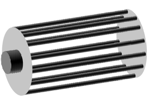
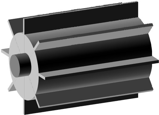
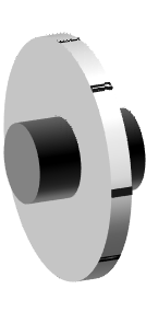
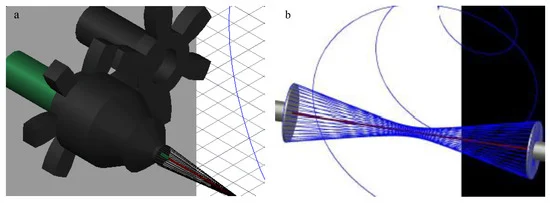
AutoCAD images of (a) the final design of the modified air-gap electrospinning with motor setup, signifying the stationary (green) and rotating (black) parts. (b) A simplified setup demonstrating the wrapping of electrospun fibers (blue) around the glass fiber (red) [Linder et al 2020]

Steering electrode, which uses like or opposing polarity, can be used to deflect or steer the electrospinning jet [Arras et al 2012]. This and focusing electrodes can be very effective in taming the bending instability such that the fiber deposition area is reduced. When used in combination with a rotating collector, fibers with good alignment can be collected [Bellan et al 2006, Deitzel et al 2001]. Guiding electrode in the form of sharp edge(s), pointed needle(s) or parallel electrodes [Lee et al 2009, Teo et al 2015] is very effective in attracting the electrospinning jet. This concept has been used to fabricate nanofibrous tube with diagonal fiber alignment [Teo et al 2005] and to improve fiber alignment [Wu et al 2007, Gupta et al 2007, Arras et al 2012, Lee et al 2009, Teo et al 2015]. Teo et al (2005) compared the effect of the guiding electrodes on fiber alignment on a rotating rod collector. In the experiment three different setups were used, one is a stainless steel rod, the second is a Teflon tube with aluminium strips as guiding electrodes and the third is a Teflon tube with sharp edge guiding electrodes. With the same rotation speed, the fibers were randomly oriented on the stainless steel rod. With strip guiding electrodes, distinct fiber alignment can be observed. In the final setup with sharp edge guiding electrodes, the fiber alignment was significantly better than the strip guiding electrodes. Teflon tubes were used in the second and third setup such that the guiding electrodes have a greater influence on the direction of electrospinning jet movement. Sharp edge guiding electrodes were better able to narrow the path of the electrospinning jet in the direction that is orthogonal to the long axis of the tube collector which results in good fiber alignment. Even more amazing is the work by Sundaray where he uses a pin inside a tube to guide the electrospinning jet to create cross-aligned nanofibers on a tube [Sundaray et al 2004].


Comparison of fiber alignment between fibers collected with [Top] strips guiding electrodes and [Bottom] sharp edge guiding electrodes. [Teo et al 2005]
Auxiliary electrodes
Schematic illustration of various electrodes.

Using a multiple electrodes system, Shao et al (2021) demonstrated the use of a pair focusing electrodes and parallel electrodes collector to produce highly aligned polyacrylonitrile (PAN) fibers. In their setup, an insulating PTFE Vee-shield was used as the focusing electrodes. As a focusing electrode, the Vee-shield with a slit at the bottom confines the electric potential between the needle and the collector such that it runs parallel to the slit. This causes the electrospinning jet to oscillate along the opening at the bottom of the Vee-shield. To further encourage the electrospinning jet to oscillate along the length of the opening, a cellulose tape covers the length of the grounded electrode at the bottom of the slit such that only the ends of the grounded electrode are exposed. As the cellulose tape masks the middle portion of the grounded electrode, the collector effectively functions as a parallel electrode collector. To incorporate a continuous spooling of the cellulose tape, an entry and exit opening was added near to the end of the exposed grounded electrode. This way, both focusing electrodes and the parallel electrode collector direct the electrospinning jet to oscillate between both ends of the parallel electrode and the spooling cellulose tape was able to pick up highly aligned polyacrylonitrile (PAN) fibers.


Schematic illustration of a vee-shield. (xv) PTFE Vee-shield; (xvi and xvi') back and front edges of the ground electrode respectively; (xvii) strip of cellulose paper; (xviii) perimeter where the majority of the aligned fibres are deposited; and (xix) slot in the PTFE where the cellulose substrate is fed through when spooling (a similar slot is present on the opposite end) [Shao et al 2021]

Rotating disc collector Pin in cylinder
Rotating disc collector Pin in cylinder to direct electrospinning jet
nanofibrous tube setup
Diagonally aligned nanofibers [Teo et al 2005] AC guiding electrode [Lee et al 2009]
nanofibrous tube setup  
Aligned fibers using guiding electrode [Teo et al 2005]  
A limitation of the mechanical system for collecting aligned fibers is the air turbulence generated by the fast moving collector. Reduction of the air turbulence has been shown to improve fiber alignment and production of nanofibers due to less wastage. Reduction of the influence of air turbulence on the incoming fibers can be achieved by the installation of an air-shield. Krishnamoorthy et al (2011) has successfully demonstrated this with the combination of a disk collector. Note that the sharp edge of the disk collector will also help to guide the electrospinning jet to its edge. Nguyen et al (2016) cleverly used the air shield to double up as an electrostatic shield to restrict electrospinning jet deposition of the fibers to the gap between. This has been shown to significantly improve the alignment of the fibers collected compared to conventional rotating collector.
Electrospinning with air shield
Fig 1. Rotating disk with (Left) enclosed-air-shield with air-hood (front view), (Right) air-hood arrangement (top view) for the turbulent air to escape [Krishnamoorthy et al Journal of Nanomaterials, vol. 2011, Article ID 739241, 7 pages, doi.org/10.1155/2011/739241. This work is licensed under a Creative Commons Attribution 3.0 Unported License.]
Electrospinning with air shield
Fig 2. The TiO2 ceramic nanofibres of diameter 98±20 nm were collected using the rotating disc at 750 rpm; (left) without air shield and (right) using enclosed-air-shield with air-hood. [Krishnamoorthy et al Journal of Nanomaterials, vol. 2011, Article ID 739241, 7 pages, doi.org/10.1155/2011/739241. This work is licensed under a Creative Commons Attribution 3.0 Unported License.]

Illustration of the air and electrostatic shield for diversion of air turbulence and narrowing the distribution of the fiber for collection of aligned fibers as reported by Nguyen et al (2016).

Near-field electrospinning has emerged as a possible method to get a highly ordered structure as the fiber is deposited while the electrospinning jet is still at its stable phase. When combined with a guiding electrode and a corresponding translating collector, researchers were able to construct an ordered three-dimensional structure. Zheng et al (2021) used near field electrospinning and a sharp pin guiding electrode below the collector as a means of getting highly precise and accurate fiber deposition. The role of the guiding electrode is to focus the electrical field and with near field electrospinning. Using polyethylene oxide (PEO) as the model polymer, they were able to stack up to layers of fibers to create 3D complex structures with 10 to 80 fibers layers and height of 10 to 110 µ. With solution electrospinning, residual solvents present in the deposited fibers may also facilitate migration of charges on the fiber to the ground which allow more layers of fiber to be stacked. A parameter that affects fiber placement is the collector motion velocity. A higher velocity would increase fiber placement accuracy as the polymer jet is stretched and reduces fiber diameter. A higher applied voltage also led to better fiber alignment due to greater focusing of the electric field between the nozzle and the guiding electrode. Although up to 80 fiber layers have been constructed, the effect of residual charges and the shielding of the electric field by the higher fiber layer cannot be prevented. Hence the accuracy and precision of the fiber deposition will be reduced as the layers build up. For a 60-layer fiber wall, Zheng et al (2021) reported a width of 94.3 µm and height of 102.2 µm although the fiber thickness is about 1.8 µm.


Guiding electrode setup for stacking layers of electrospun polyethylene oxide (PEO) fibers [Zheng et al 2021]
Published date: 14 August 2012
Last updated: 22 November 2022


Comments
[+]


Google Ad.