The electrospinning jet path can be easily influenced by the electric field and its profile due to the presence of electrical charges on the surface of the electrospinning jet. Even the position of the probe transmitting the current from the high voltage power supply to the needle tip is known to affect the direction of the electrospinning jet [Memarian et al 2013].
The electric field profile can be manipulated through clever use of auxiliary electrodes such as base electrode,
focusing electrodes,
steering electrodes and
guiding electrodes.
Modeling of the electric field profile may then be used to predict the path of the electrospinning jet. By controlling the jet path, ordered fibrous structures may be constructed or targeted fiber deposition may be achieved.

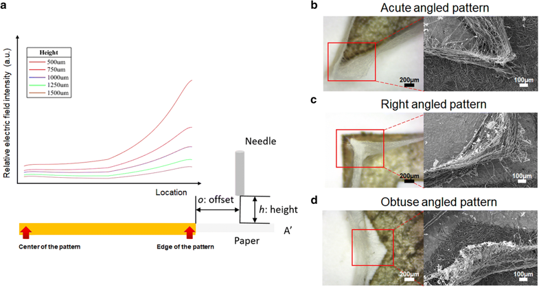
Experiments have shown that electrospun fibers are very sensitive to slight variation in the electric field profile. Kim et al (2018) used inkjet printing with conductive Ag nanoparticles loaded ink to form patterns on a paper as a target for near field electrospun fibers. The conductive printed pattern served as a guiding electrode for the electrospinning jet. Poly(vinylidene fluoride) (PVDF) solution was electrospun from a height of 750 µm and a 150 µm offset from the edge of the pattern. The sensitivity of the electrospinning jet towards the electric field can be seen as the fibers are stacked on the edge of the conductive pattern where the relative electric field was much higher at the edge than at its center. When the pattern lines formed acute angle, right-angle or obtuse angle, the accuracy of the deposited fibers are influenced by slight changes in the relative electric field. From acute angle to right-angle, the electric field singularity increases from the edge to the intersection between the lines. In this case, the fibers were stacked directly on the edge of the line and to the middle of the intersection. For lines forming obtuse angle, the deposited fibers followed the edge of the lines by veered off the line at the intersection.
However, this also means that it is difficult to maintain a stable electric field profile as continuous deposition of nanofibers with their
residual charges[Collins et al 2012] creates a fluctuating electric field. The sensitivity of the jet path to electric field profile can be
seen in multiple spinnerets electrospinning where each jet will deposit fiber on separate patches initially. In some setups, the collector is able to
alter the electric field such that it directs nanofiber deposition as in the case of parallel electrodes collector. However, a significant drawback of
this technique is that the influence of the collector on the deposition behavior soon diminishes as the nanofiber layer and the corresponding residual charges builds up.
Presence of residual charges on conventional plate collector may also divert the electrospinning jet away from the collector.
In electrospinning, the charged jet may also be attracted to the surrounding objects apart from the designated collector. This loss of fibers may be significant especially for mass production. Controlling the jet path using secondary electrodes may be used to divert the electrospinning jet away from the surrounding objects and towards the collector. Viswanadam et al (2013) has demonstrated a yield increase of fiber collection from 23% to 87% based on this concept.
Published date: 10 Jun 2012
Last updated: 26 February 2019
▼ Reference
-
Collins G, Federici J, Imura Y, Catalani L H (2012) Charge generation, charge transport, and residual charge in the electrospinning of polymers: A review of issues and complications. J. Appl. Phys. 111, 044701.
Open access
-
Kim J, Maeng B, Park J. Characterization of 3D electrospinning on inkjet printed conductive pattern on paper. Micro and Nano Systems Letters 2018, 6:12.
Open access
-
Memarian F, Zeighami F, Tehran M A, Latifi M. HV probe angle effect on jet bending instability direction in electrospinning systems. The International Istanbul Textile Congress 2013, May 30 to June 1, Istanbul, Turkey.
-
Viswanadam G, Chase G G. Modified electric fields to control the direction of electrospinning jets. Polymer 2013; 54: 1397.
▲ Close list