Home | About | Contact


Multiple Orifices

Pros:
  • Easy to setup
  • Relatively uniform fiber diameter
  • Relatively low voltage
  • Flexibility in fabricating fibers with different configurations (core-sheath, multicomponent etc.)*
  • Flexibility to introduce different polymer types*

Cons:
  • Clogging of orifice
  • Optimization of needle arrangement is a challenge.
  • Difficulty in maintaining uniform feed rate through each orifice.
*Applicable for needle-base electrospinning

Needle / Nozzle

For a standard lab based electrospinning setup a needle is used to dispense and to apply charges to the electrospinning solution. To increase the output of the setup, more needles can be used. However, the configuration of the needle arrangement needs to be optimized to reduce charge interference between them [Theron et al 2005]. With just one more needle, the maximum field strength will drop significantly compared to a single needle [Angammana and Jayaram 2011]. For nozzles arranged in arrays, the electrical field gets progressively weaker from the edge to the center. The weakening in electric field becomes more significant when the distance between the nozzles is reduced. Even at inter-nozzle distance of 5 cm, there is still discrepancy in the electric field across the surface [Krucinska et al 2009]. This may result in less stretching of the solution drops closer to the center.


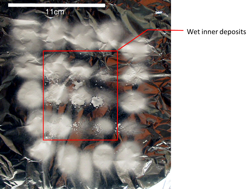
Wet fiber deposits from the inner electrospinning nozzles.

When multiple nozzles are arranged such that there is a center nozzle surrounded by other nozzles, the Coulomb forces exerted by the surrounding jets forces the inner jet to travel in a more direct trajectory towards the collector. This may result in wet deposited fibers from the inner jets necessitating an increase in the tip to collector distance to allow sufficient flight time to get dry fibers [Varesano et al 2009]. Fluctuations in the electric field at the nozzle tip due to interference with the adjacent jets may also temporarily arrest electrospinning from the central nozzle before it restarts. When this happens, a larger solution stream may deposit thick wet fibers on the collector [Varesano et al 2010].

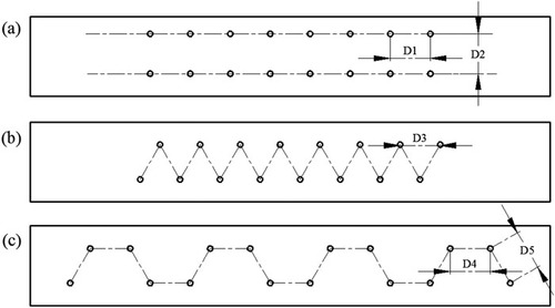
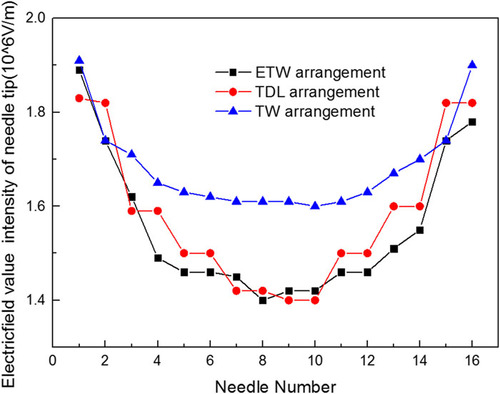
Interference of the electric field between each nozzle is the main limiting factor to the number of nozzles that can be packed and the output Fiber quality. However, it is possible to reduce the detrimental effect of the electric field interference by optimising the nozzle array configuration. In a study by Zhu et al (2018), they found that nozzles arranged in a trapezoid configuration creates a more uniform electric field compared to double-line linear arrangement and equilateral triangle wave arrangement. Although the nozzles at the ends still have the highest electrical field value, the drop in electric field for the middle nozzles from the trapezoid arrangement is less than the other two arrangements. With 16 nozzles, both double-line linear arrangement and equilateral triangle wave arrangement exhibited dripping at the middle nozzles. Only the trapezoid arrangement showed no droplets on the collector. The trapezoid arrangement was used for 32 nozzles and there were no droplets on the collector. This nozzle configuration has the potential to increase the production output of needle-based electrospinning.


Three types of multi-needles arrangement of electrospinning head [Zhu et al 2018].

The comparison of the electric field for three different needle arrangements [Zhu et al 2018].

The main challenge in nozzle based electrospinning is the uneven distribution of electric field strength with the field strength being highest on the periphery and lowest at the center nozzles. This reduces the electrospinning output from the nozzles nearest to the center of the nozzle array. To improve electrospinning in multi-nozzles setup, it is important to create a more uniform electric field from the nozzle to the collector. Jiang et al (2019) demonstrated the electrospinning potential of having a linear row of nozzles arranged in a vertical arc or U shape from the collector, with the center nozzle at a distance nearest to the collector and the distance progressively increasing towards the ends. This creates a more uniform electric field since the shielded center nozzles are now nearer to the collector. By varying the depth of the arc, the electric field strength across the nozzles can be adjusted. Comparing the electrospinning of polyethylene oxide (PEO) solution from 9 nozzles arranged linearly, between nozzle tips arranged in the same plane and in an arc, the former had solution dripping from the center nozzles while the latter showed continuous electrospinning across all 9 nozzles at optimal arc arrangement. To facilitate electrospinning from nozzles arranged in a vertical arc arrangement, Zheng et al (2020) applied a sheath gas around each electrospinning jet which is also known as electroblowing. The sheath gas provides additional drawing force on the electrospinning jet hence a lower voltage may be used. The sheath gas and lower voltage applied also reduces electrostatic repulsion between adjacent electrospinning jets. The diameters of the fiber collected decreases with a higher sheath gas pressure and there is a lower diameter distribution. In multiple nozzle electrospinning, the electrospinning jets from the nozzles at the center still give a larger fiber diameter compared to those from the edges despite a vertical arc arrangement. Even if the electric field strength from the center nozzles may be nearly as strong as those from the edges due to the nozzle vertical distance adjustments, there are other factors such as reduced traveling distance of the electrospinning jet and higher residual charges at the center collector region which still result in higher diameters in the fibers collected in the center compared to the edges. The addition of sheath gas helps to reduce the difference in the electrospinning conditions by providing a uniform drawing force from the sheath gas across all the nozzles, dispersing the residual charges from the collected fibers and restricting the area which the electrospinning jet can travel across all the nozzles. Their studies showed that this significantly reduces the differences in the fiber diameters from the fibers collected at the center and the edges.

A shield ring surrounding multiple spinnerets has been shown to facilitate electrospinning in all the nozzles within. Without a shield ring, electrospinning jets from multiple nozzles tend to diverge from one another due to Coulomb forces. Having a ring shield suppresses the outward divergence of the jets and was able to encourage the jets to maintain a straight path from the nozzle tip [Kim et al 2006]. The collected electrospun fibers were found to have a larger fiber diameter compared to fibers electrospun without the ring shield. This may be the result of reduced flight time due to shorter traveling distance [Kim et al 2006]. Yang et al (2010) was able to pack up to 37 needles in a hexagonal arrangement within a shield ring for electrospinning with inter-needle distance of 1 cm. By optimizing the diameter of the shield ring surrounding the needles and its height according to the number of needles, they were able to obtain a fairly uniform electric field across the tip of the needles. Although distinct patches of fibers were formed initially, fiber distribution over the whole deposition area became more uniform after an hour and continuous spinning has been tested without any issues for 4 h. With increasing number of needles, the minimum working distance between the tip and the collector also increases and it reaches 35 to 38.5 cm for 37 needles.

There are several factors which influence the inter-nozzle distance. In a typical electrospinning setup, the distance between the nozzle tip and the collector is about 10 cm. However, in near field electrospinning, this distance is reduced to about 5 mm. At such close proximity between the tip and the collector, the nozzles can be placed closer to one another. Han et al (2015) showed using triple nozzles that with a distance between tip and collector of 4 mm, the nozzle spacing is only 2 mm. Increasing distance between tip and collector resulted in greater mutual distance of deposition which reflects greater interference between the electrospinning jets. Since near field electrospinning has been demonstrated to control fiber deposition, this may be used for mass spinning of aligned fibers.

Multiple nozzles method has been used successfully to fabricate aligned fibers with a rotating drum. Krishnamoorthy et al (2012) used twenty four nozzles arranged in a rectangular array with inter-nozzle distance of 1.1 cm. With an applied voltage of 15 kV, distance to collector distance of 10 cm and drum rotation speed of 1200 rpm, they were able to produce fairly aligned tin precursor/polypyrrolidone fibers.

The length of the nozzle may also have an effect on the electric field profile. Using finite element simulation, it was found that longer needle length reduces the electric field intensity [Kang et al 2013]. Thus it is recommended that a shorter needle length is used in such a system. To mitigate the effect of electric field emitting from the needle length interfering with the electrospinning space electric field, Kumar et al (2010) used a plastic filter to reduce the exposed needle length to a minimum such that the opening of the needle was flushed to the surface of the plastic filter. A few notable differences in the electrospinning behavior and output were found between having a plastic filter and conventional exposed needles. Interference between the electrospinning jets was much less with the plastic filter and fiber deposition on the collector was much more uniform compared to distinct deposition areas for multiple exposed needles electrospinning. Although the charges present on the individual jets still influence one another, it is much less compared to the electric field "silos" created by individual needles. Fiber diameter distribution from the plastic filter electrospinning was also relatively uniform while exposed needles electrospinning showed bimodal fiber diameters which is probably due to differences in electric field between needles.

Multiple nozzle
Multiple linearly arranged nozzles for fiber production (See publication)

To overcome the limitation of fixing needle density for electrospinning, needle-less technology has been developed to improve the production rate. Although needle-less electrospinning has been shown the potential to significantly increase the production rate, the quality of the fibers in terms of its fiber diameter distribution, electrospun from a setup with needle is still better. Electrospun fibers using a needle setup generally gives a smaller diameter compared to needle-less electrospinning. These results are consistent for both polymer [Huang et al 2012] and inorganic fibers [Vahtrus et al 2015] derived from electrospinning. At optimum feedrate for needle-based electrospinnjng, stretching of the solution droplet at the tip of the nozzle can be maximised without breaking the continuous jet. Someshwararao et al (2018) showed that a reduction of solution feedrate from 1.2 ml/h to 0.6 ml/h for electrospinning of titanium tetraisopropoxide (TTIP)/PVP solution was able to reduce the electrospun fiber diameter from 247 nm to 111 nm. The electrospun nanofibers with reduced diameters were smooth and without any beads. In contrast, free surface electrospinning does not have control over the amount of solution that are drawn off from the surface in the electrospinning jet. Other observations such as looser fibrous membrane and higher crystallinity from needle-less electrospinning compared to needle electrospinning has been observed for spinning polystyrene although this may be dependent on the electrospinning solution and the parameters [Huang et al 2012]. While needleless electrospinning may have an edge over needle-based electrospinning in terms of productivity, needle-based electrospinning still retains the advantage where fiber quality is more important.


Video of FLUIDNATEK LE-100 electrospinning unit with multiple nozzles.


Porous surface

Another way of introducing orifices for electrospinning is to use a porous surface from a reservoir. The solution dispenser may come in the form of a cylinder with porous surface which solution may flow through the wall and to the outer surface [Dosunmu et al 2006].

While this setup is able to introduce many orifices for multiple electrospinning jet, it also have several critical disadvantages. Cleaning of clogged pores between spinning will be much more difficult although it can still be carried out by flushing with copious amount of solvents. Maintaining a uniform feed rate through each pore will be almost impossible. If the feed rate is too high, excess solution on the surface of the outer wall will make this spinning more like free surface spinning.

Porous cylinder


Others

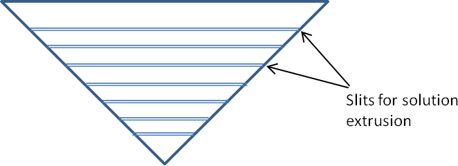
There are many other methods of introducing solution for electrospinning without the use of a needle. A cylinder with regular holes[Varabhas et al 2008] or conical wire coil[Wang et al 2009] have been used successfully for electrospinning. The advantage of these systems is that there is no needle protrusion that creates auxiliary electric field lines that interferes with the electrospinning jet. This may result in better fiber distribution at the collector and more uniform fiber diameter. Srivastava et al (2007) used poly(dimethyl siloxane) (PDMS) to construct a multi-orifices spinneret with channels in the PDMS block leading from an input point to several output orifices. At an inter-orifice distance of 8 mm, they were able to achieve more uniform and dense nanofibrous mats. This contrasts with conventional unmodified multi-needles electrospinning which show distinct deposition region from each needle.

Pictorial illustration of conical wire coil[Wang et al 2009]. Click on image to enlarge. Pictorial illustration of cylinder with regular hole[Varabhas et al 2008]. Click on image to enlarge.

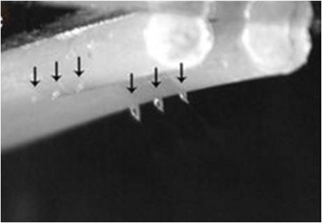
A detailed study of tube nozzle electrospinning was carried out by Fang et al (2017). In their setup, evenly spaced holes (nozzles), 5 mm apart, were made along a low density polyethylene tube. Each hole (nozzle) has a diameter of 0.2 mm and photopatternable epoxy SU-8 was used as the material for electrospinning. With more nozzles used, the voltages required for initiating electrospinning also increases. During electrospinning, the Taylor cone from each nozzle diverges due to the mutual repulsion from the electrospnning jets. With 4 nozzles and 8 nozzles system, membrane thickness increases linearly until it starts to plateau off at 240s. This is probably due to increasing repulsion caused by residual charges present on the deposited membrane.

Multi-tube electrospinning using 2 tubes with 3 nozzles each showing Taylor cones. [Fang et al Micro and Nano Systems Letters 2017; 5: 10. This work is licensed under a Creative Commons Attribution 4.0 International.]

Published date: 5 August 2012
Last updated: 08 September 2020


Comments
[+]


Google Ad.