Electrospinning can be used to fabricate nanotubes from polymers and inorganic materials. There are also a few different ways in which this can be done although it typically requires at least a second step following electrospinning. For polymer nanotubes, core-shell electrospinning is most often used and this method may also be used for producing inorganic nanotubes. For inorganic nanotubes, a sintering process is typically required to convert the precursors or to burn off the organic core template. In some special cases, the molecules would self-organize such that nanotubes are formed after heat treatment.
Core-shell Electrospinning
Hollow fiber constructed using coaxial electrospinning is usually with a temporary material as the core and the actual material as the shell. Where a sacrificial core material is used, it is usually of lower molecular weight to facilitate removal post electrospinning. Liu et al (2021) combined the technique of core-shell electrospinning and incorporating a sacrificial material on the shell of the fiber to create hollow porous microfibers. To electrospin hollow porous polybutylene adipate terephthalate (PBAT) microfibers, a co-axial nozzle was used in the electrospinning. The outer solution was PBAT and low molecular weight polyethylene glycol (PEG) with PEG as the sacrificial material. The core sacrificial material was polyvinyl acetate (PVA) solution. After electrospinning, the core-shell fibers were ultrasonicated in pure water at 70°C for 12 h to dissolve the PEG and PVA. The resultant fibers have a hollow core with porous walls. Qavi et al (2023) also used co-axial electrospinning to construct porous-wall tubes. Instead of using a sacrificial material for the wall, they used polycaprolactone (PCL) dissolved in dichloromethane (DCM) as the sheath solution. Due to the high volatility of DCM, PCL goes through phase separation during electrospinning to form a porous wall. Polyethylene oxide (PEO) was used as the core solution and the electrospun PCL sheath and PEO core fibers were soaked in DI water for an hour to remove the PEO core to form tubes. However, it was not obvious whether the pores on the tube walls were through-hole pores or pits.
Oil may also be used as the temporary material as it is relatively easier to remove them compared to polymers. Hollow fibers may also be formed using a core solution in which the solvent used is a non-solvent for the shell material. This causes solidification of the shell material at the interface during electrospinning and subsequent solvent vaporization encourages the core material to migrate to the interface thus forming a hollow fiber [Na et al 2012]. In the construction of ceramic hollow fiber, other polymers may be used in the core as they can be removed during the sintering process. In a novel coaxial electrospinning technique, air, instead of solution was used as the core "material".
Using air as the core "material" means that post spinning process is not necessary. Yu et al (2014) examined the factors that allows for the fabrication of Fe3O4/Eu(BA)3phen/PVP hollow fibers. Their study showed that solvent selection plays an important role in the formation of hollow fibers by blowing air through its core. While Fe3O4/Eu(BA)3phen/PVP was able to form hollow fiber using chloroform, CHCl3 as the solvent, solid fibers were formed using DMF. Yu et al (2014) hypothesized that low surface tension and higher evaporation rate of CHCl3 is the reason for the formation of the hollow fibers. A high surface tension solvent will certainly overcome the supporting air blowing at the core and cause the collapsed or contraction of the wall leading to the formation of solid fibers. A higher evaporation rate facilitates the solidification and formation of an intact wall soon after leaving the nozzle tip.
Unique hollow ceramic composite nanofibers have also been constructed with clever selection of core and shell material. Chang et al (2008) used coaxial electrospinning to fabricate TiO2 hollow nanofibers with silver nanoparticles littering the inner walls of the hollow fibers. PVP solution was used as the electrospinning agent for titanium n-butyloxide (Ti(OC4H9)4 at the shell and silver nitrate AgNO3 at the core. Following calcination of the electrospun composite fibers, the TiO2 hollow nanofibers fibers with AgO2 coated interior was found to exhibit greater photocatalytic activities toward decomposition of methylene blue compared to other nanostructured TiO2 materials such as mesoporous AgTiO2 blended fibers, TiO2 hollow nanofibers, TiO2 nanofibers and TiO2 powders. A similar technique is to use mineral oil containing nanoparticles in the core and an electrospinnable polymer for the shell. Wang et al (2013) constructed a hollow carbon nanofiber with silicon nanoparticles along the inner wall using this concept. Polyacrylonitrile solution was used for electrospinning of the nanofiber shell and the core is a mixture of silicon nanoparticles and mineral oil.
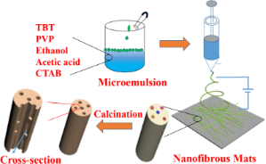
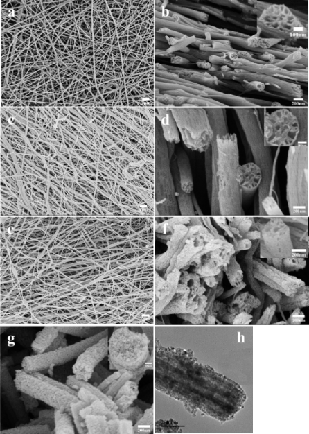
Electrospinning of emulsions have been shown to generate hollow tubes within the fiber. This may be due to the elongation and merging of droplets in the solution during electrospinning. Zhang et al (2017) was able to construct TiO2 nanofibers with axially aligned channels by first electrospinning tetrabutyl titanate (TBT) with paraffin oil followed by calcination. The emulsion is formed by butoxyl groups in TBT serving as additional surfactant to cetyltrimethylammonium bromide surfactant for encapsulation of paraffin oil. Polyvinyl pyrrolidone (PVP) was added as a carrier to facilitate formation of fibers. Observation of the calcinated nanofiber under Transmission electron microscope (TEM) and scanning electron microscope (SEM) showed presence of multiple channels inside the nanofibers. Without paraffin oil, solid fibers were formed. In some cases, linear arrangement of immiscible droplets along the core of the fiber was able to form core-shell fibers [Wang et al 2014].
Organic core template
Electrospun nanofibers are often used in the construction of hollow tubes, in particular, inorganic tubes. These are often prepared by coating the fibers with the desired material followed by the removal of the fiber core. The challenge is to get a uniform coating around the fibers so that complete tubes can be obtained. Huang et al (2024) used electrospinning to produce polystyrene (PS) nanofibers. HfO2 precursor solution was prepared using hafnium(IV) chloride (HfCl4) dissolved in organic solvent (propylene glycol methyl ether, PGME). The electrospun PS fibers were coated with the HfO2 precursor solution using dip coating method. An annealing temperature of 800 °C was used to pyrolyze PS to give crystalline HfO2 hollow fibers.
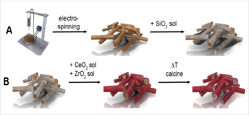
Schneider and Naumann (2014) used dip coating to deposit tetra-ethoxysilane solution on polystyrene fibers followed by calcination. A second coating was carried out using spray coating to deposit a layer of cerium (III) chloride and zirconium oxychloride sol over the polystyrene/silica composite fibers. A second of calcination at 750 °C for 4 hours were carried out to form CeO2/ZrO2@SiO2 composite tubes.
Another method of coating fibers is to use chemical vapor deposition which can be used to deposit organic polymers and inorganic materials. Liu (2004) used chemical vapor deposition to coat polylactide template fiber with poly(para-xylylene). Polylactide core was shown to be removable by boiling in chloroform for 12 hours or heat treatment at 280°C for 8 hours. Kim et al (2008) used atomic layer deposition, a type of chemical vapor deposition technique to deposit TiO2 precursor (titanium tetraisopropyl oxide) on poly(vinyl pyrrolidone) (PVP) fibers. Calcination at 500°C was used to remove the inner PVP core. Atomic Layer Deposition (ALD) was also used by Dicastillo et al (2018) to deposit TiO2 on electrospun polyvinyl alcohol (PVA) template for the construction of TiO2 nanotubes. In their setup, Tetrakis (dimethylamide) titanium (TDMAT) and ultra-pure water were used as Ti and oxide sources, respectively. Following deposition of TiO2 on PVA nanofibers, the PVA template was removed by washing with water and by sintering. When a temperature of 200 ° was used during the ALD process, the TiO2 coated PVA nanofibers showed a bluish hue. When PVA was removed by washing, the membrane retained its bluish hue. However, when the membrane was sintered at 400 °C, the color of the membrane changes from blue to white. This color change has been attributed to transformation of the TiO2 from amorphous to crystalline phase. The TiO2 nanotube showed a wall thicknesses approximately 19-22 nm whether it is obtained by washing, sintering at 400 °C or at 600 °C. Atomic layer deposition was also used by Keri (2018) et al for coating of electrospun water soluble polyvinyl alcohol (PVA) and polyvinyl pyrrolidone (PVP) nanofibers with Al2O3. The temple core we removed by dissolution in water at 60°C and annealing at 550°C. Both template removal techniques resulted in amorphous Al2O3 nanotubes. Using the dissolution method, traces of polymers remained in the nanotube as shown by the presence of smaller intensity peak under FTIR scan. However, with annealing, none of the peaks attributable to the polymers can be found. This annealing will give a more complete removal of the polymers. Observation of the nanotubes following template removal showed some breakages from the samples that went through annealing. The breakages may be due to gases pushing through the Al2O3 layer during decomposition.
To construct a metallic tube, metal material may be coated on template fibers by sputtering. Sintering is then carried out to remove the organic core. Pantojas et al (2008) coated polyethylene oxide fibers with palladium using sputtering. A sputtering duration of more than 250s is required to form complete tubes after sintering. However, the thickness of the wall section of the cylinder is not uniform due to line-of-sight deposition.
Similar to sputtering, thermal evaporation is another method of depositing inorganic materials and metal. A study by Wu et al (2013) showed that the choice of template polymer fiber has an influence on the quality of the tube formed and in their case, nano-trough since they are only interested in depositing on one side of the nanofibrous membrane. They have selected polyvinylpyrrolidone fiber for fabrication of nano-trough out of gold, platinum, silicon and ITO. Polyvinyl alcohol nanofibers were selected for copper, silver and aluminum. They first transfer the coated nanofibers on selected substrates such as plastic, paper, glass and textile without any surface treatment and using standard thin-film deposition technique. Removal of the core material is by using water or organic solvent to form nano-trough on the substrate surface. The adhesion between the nano-trough and the substrate was sufficient to resist peeling using scotch tape.
Coating of electrospun fibers with inorganic precursors or nanoparticles may be carried by directly electrospinning into a coagulation bath containing the precursor or nanoparticles. Im et al (2012) used this concept to prepare carbon/TiO2 nanotubes. In their setup, poly(vinyl alcohol) (PVA) aqueous solution was directly electrospun into a coagulation bath containing titanium (IV) tetraisopropoxide (TTIP) solution. PVA fibers were coated with TTIP and the resultant composite was heat-treated to form carbon/TiO2 nanotubes.
Self-Organization
Distribution and orientation of molecules and ions are influenced by several factors such as crystallinity, interaction between material mixture and molecular mobility. Tsaroom et al (2011) observed the formation of core-shell polymer-metal salt fibers with the positively charged metal salt concentrated at the core of the fibers after electrospinning with high positive charge. However, this was only seen when the metal salt is mixed with polyethylene oxide polymer but not with polyacrylic acid. It was hypothesized that the interaction between the negative ions of polyacrylic acid with the positive metal salt restricted any metal-salt ions distribution under the influence of the positive external charge. It is with polyethylene oxide, which is neutral, that core-shell structure was formed with metal salt rich core. However, application of negative high voltage does not see a concentration shift of the positive metal towards the shell. This has been attributed to crystallization of polyethylene oxide from the surface which prevented the aggregation of metal-salt at the surface.
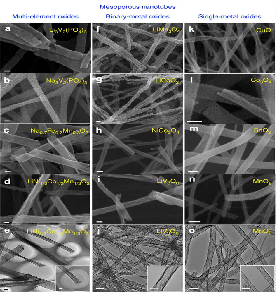
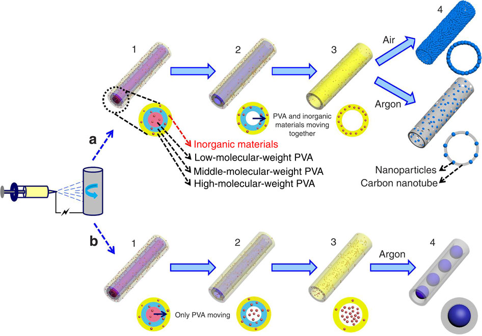
Through deliberate selection of the material to be electrospun and controlled pyrolysis, the precursor material may be encouraged to form tubes after the pyrolysis process. Niu et al (2015) demonstrated this with by preparing precursor solution with a mixture of low-, middle- and high- molecular weight polyvinyl alcohol. During electrospinning, they hypothesized that the low-, middle- and high- molecular weight polyvinyl alcohol will separate to form three layers with the lowest molecular weight PVA in the middle instead of uniform distribution. They supported this hypothesis by replacing low molecular weight PVA with polyvinyl pyrrolidone (PVP) for electrospinning and followed by the removal of PVP to give hollow tube. The composite electrospun precursor/PVA fibers nanofibers were sintered and nanotubes were formed. This was attributed to sequential pyrolysis where the low molecular weight PVA first pyrolyze, shrinks and move towards the higher molecular weight interfaces and carried with it the inorganic ions as the temperature increases. This method successfully constructed nanotubes of Li3V2(PO4)3, Na3V2(PO4)3, Na0.7Fe0.7Mn0.3O2, LiNi1/3Co1/3O2, LiMn2O4, LiCoO2, NiCo2O4, CuO, SnO2, MnO2 and others.
Adding PVP to a solution of graphite oxide (GO) and SnCl2 for electrospinning, Wang et al (2019) was able to construct hollow graphene oxide/SnO2 fibers after sintering. Wang et al (2019) hypothesized that during heating PVP migrated into the inner space between GO nanosheets and SnO2 nanoparticles nucleated on the GO nanosheets. It may be possible that as PVP melts and decomposes, the exiting gas pushes the GO nanosheets with the SnO2 nanoparticles towards the outer edges of the fiber with semi-molten PVP remaining at the core. Upon full decomposition of PVP, a hollow tube structure is formed. Movement of decomposing volatile byproducts carrying small SnO2 crystals from the core of electrospun fibers to the surface have also been proposed as the mechanism for the formation of SnO2 nanotubes after sintering of electrospun SnCl2.2H2O/polyvinyl butyral (PVB) fibers [Suzuki et al (2020)]. A heating temperature of 500 °C was needed to form hollow fibers from electrospun SnO2 precursor fibers. Below this temperature, only smooth and solid fibers were formed. Observation of the fibers using TEM at progressively higher heating temperature showed the formation of a core fiber at temperatures between 230 °C and 600 °:C which eventually disappeared to form a hollow fiber. At a temperature of 500 °C, there was a higher concentration of Sn and O ions on the surface. Suzuki et al (2020) hypothesized that higher solubility of Sn ions in ethanol encourages the diffusion of the ions to the outer surface compared to PVB. Movement of oxidised organic compounds at the core may have also carried small SnO2 crystals to the surface of the fibers. SnO2 crystals at the surface of the fibers would grow in the presence of higher O in the environment and as more Si ions were carried to the surface. SnO2 nanotubes were formed at the end of the heat treatment. Ranjith et al (2020) created a FeMoO4 nanotubes using co-polymeric precursors polyacrylonitrile (PAN) and poly(methyl methacrylate) (PMMA) for electrospinning with the Fe and Mo sources. The electrospun FeMoO4-PAN/PMMA nanofibers (NF) were thermally decomposed to produce tubular FeMoO4 NFs. Both PAN and PMMA are needed for the formation of the nanotube. While the mechanism has not been discussed in their report, they suggested that earlier decomposition of PMMA during the heating process and the stability offered by PAN may have helped in the formation of the nanotubes. When PMMA alone was used to prepare the electrospun FeMoO4-PMMA fibers, there was a complete collapse of the fibrous morphology after annealing. On the other hand, the use of PAN alone resulted in FeMoO4 NF with a solid core. The addition of PAN may favor the formation of denser carbon linkages to hold the fiber structure during nucleation and growth of FeMoO4 grains.
In the construction of rutile titania nanotubes through electrospinning of a solution of titania precursor and polyvinylpyrrolidone (PVP) into fibers followed by calcination, Kang et al (2021) found that its formation is influenced by initial concentration and calcination profile. They identified 3 main processes for the calcination of the electrospun precursor fibers to form nanotubes. They are surface pyrolysis, particle growth and gasification of the polymer. At the onset of heat treatment, surface pyrolysis causes the surface polymer to burn off followed by the consolidation and growth of ceramic ions to form a shell. As polymer degradation progresses towards the core of the fiber, gasified polymer brings the ceramic ions towards the shell where the gasified polymer escapes while the ceramic ions are trapped by the shell layer. At calcination temperature of 950 °C, grain growth dominates and closes in on the hollow core to form a solid core fiber. Soaking of the fibers at high temperature also results in the formation of solid core fiber. The concentration of the solution also influences the ability to form nanotubes following calculations. At low concentration, the heat treated fibers showed incomplete walls or form flakes. Increasing solution concentration increases the formation of intact nanotube walls and wall thickness. Further increase in concentration results in the encroachment of the inner tube by the wall until a solid fiber is formed.
Using the concept of emulsion electrospinning with flow characteristic similar to the use of different molecular weight polymers, a lower density liquid may be added to a precursor solution for the fabrication of hollow fibers. Hou et al (2015) added paraffin oil into titania precursor solution to form micro-emulsion for electrospinning. During electrospinning, separation of the paraffin and precursor solution results in higher concentration of paraffin at the core. Following sintering, the precursor forms titania while the paraffin core completely decomposed to give hollow nanotubes.
Controlled Diffusion
Ions mobility is not restricted to during the electrospinning process. Post electrospinning treatment may also bring about ions and molecular migration or reorganization. Lu et al (2016) used controlled pre-drying of electrospun inorganic precursor nanofibers to generate core-shell magnetic nanofibers. Without pre-drying, solid core nanofibers were generated after calcination. Pre-drying at 80 °C for 24 h produces are core-shell structure and 50 °C for 24 h produces multi-core nanofibers after calcinations. Lu et al (2016) hypothesized that this is due to the diffusion of solvent and solute (ions) along the fiber's radial direction during pre-drying. With pre-drying at 80 °C, diffusion of the solvent results in low solvent concentration at the core. During calcination, a hollow core is formed. When the fibers were pre-dried at a lower temperature of 50 °C, varying solvent concentration layers in the radial direction were formed which give rise to concentric layer of solid walls across the fiber diameter. Core-shell fiber of CoAl0.1Fe1.9O4, CoFe2O4 and NiFe2O4 has been fabricated using this method. The outward diffusion of inorganic ions from the center to the surface of the nanofibers during calcination may be explained by the Kirkendall effect which describes interdiffusion between two metal atoms at the interface. The rate of diffusion is influenced by temperature and a study by Chen et al (2017) using electrospun antimony-doped tin oxides (ATO) nanofibers suggested that heating rate may be used to control Kirkendall effect and the structure of the resultant electrospun fibers. At slow heating rate (1 °C/min), the diffusion of the salt precursors are slower and this led to solid nanofibers. At higher heating rate (5 °C/min), faster ion diffusion led to the formation of fiber-in-tube structure or completely hollow nanofibers. Evidence of broken, tube-like nanofibers from higher heating rate may be due to fast gas expansion which rupture the nanofibers.
Park et al (2022) was able to construct ZnO-ZnFe2O4 hollow nanofibers from electrospinning of their precursors followed by a calcination process. The precursors were mixed with PVP solution for electrospinning and calcinated at 600 °C at a ramp rate of 3 °C/min for 3 h. Park et al (2022) attributed the formation of nanotubes to the Kirkendall effect. During the calcination process, metal ions migrate towards the surface as PVP is removed. This results in reduced concentration of metal ions in the core and the formation of hollow core structure upon full calcination. Nanotubes were fabricated across different ratios of ZnO-ZnFe2O4.
Published date: 01 December 2015
Last updated: 10 September 2024
▼ Reference
-
Chang G, Zheng X, Chen R, Chen X, Chen L, Chen Z. Silver Nanoparticles Filling in TiO2 Hollow Nanofibers by Coaxial Electrospinning. Acta Phys-Chim Sin 2008; 24: 1790.
-
Chen S, Du H, Wei Y, Peng L, Li Y, Gan L, Kang F. Fine-tuning the Cross-Sectional Architecture of Antimony-doped Tin Oxide Nanofibers as Pt Catalyst Support for Enhanced Oxygen Reduction Activity. Int. J. Electrochem. Sci. 2017; 12: 6221.
Open Access
-
Dicastillo C L, Patiño C, Galotto M J, Palma J L, Alburquenque D, Escrig J. Novel Antimicrobial Titanium Dioxide Nanotubes Obtained through a Combination of Atomic Layer Deposition and Electrospinning Technologies. Nanomaterials 2018; 8(2): 128.
Open Access
-
Hou H, Shang M, Wang L, Li W, Tang B, Yang W. Efficient Photocatalytic Activities of TiO2 Hollow Fibers with Mixed Phases and Mesoporous Walls. Scientific Reports 2015; 5: 15228.
Open Access
-
Huang M R, Chen Y F, Gautam B, Hsu Y S, Ho J H, Hsu H H, Chen J T. Hollow Hafnium Oxide (HfO2) Fibers: Using an Effective Combination of Sol-Gel, Electrospinning, and Thermal Degradation Pathway. Langmuir 2024; 40: 4732.
Open Access
-
Im J H, Yang S J, Yun C H, Park C R. Simple fabrication of carbon/TiO2 composite nanotubes showing dual functions with adsorption and photocatalytic decomposition of Rhodamine B. Nanotechnology 2012; 23: 035604.
-
Kang C S, Evans E. Synthesis and Transformation of Hollow Rutile Titania Wires by Single Spinneret Electrospinning with Sol-Gel Chemistry. Fibers. 2021; 9(3):18.
Open Access
-
Keri O, Kocsis E, Nagy ZK, Parditka B. Preparation of Al2O3 coated PVA and PVP nanofibers and Al2O3 nanotube by electrospinning and atomic layer deposition. Rev. Roum. Chim. 2018; 63(5-6): 401-407.
Open Access
-
Kim G M, Lee S M, Michler G H, Roggendorf H, Gosele U, Knez M. Nanostructured Pure Anatase Titania Tubes Replicated from Electrospun Polymer Fiber Templates by Atomic Layer Deposition. Chem Mater 2008; 20: 3085.
-
Liu T. Preparation of a Novel Micro/nano Tubes via Electrospun Fiber as a Template. J. Mater. Sci. Technol. 2004; 20: 613.
Open Access
-
Liu Y, Yang L, Chen G, Liu Z, Lu T, Yang Y, Yu J, Kang D, Yan W, He M, Qin S, Yu J, Ye C, Luo H. PBAT hollow porous microfibers prepared via electrospinning and their functionalization for potential peptide release. Materials & Design 2021: 207: 109880.
Open Access
-
Lu R, Xu M, Zhang Y, Zhou C, Zeng Y, Yang S, Song X, Zhou X. Single Capillary Electrospinning of Magnetic Core-shell Nanofibers. ChemistrySelect 2016; 1: 1510.
-
Na H, Chen P, Wong S C, Hague S, Li Q. Fabrication of PVDF/PVA microtubules by coaxial electrospinning. Polymer 2012; 53: 2736.
-
Niu C, Meng J, Wang X, Han C, Yan M, Zhao K, Xu X, Ren W, Zhao Y, Xu L, Zhang Q, Zhao D, Mai L. General synthesis of complex nanotubes by gradient electrospinning and controlled pyrolysis. Nature Communications 2015; 6: 7402.
Open Access
-
Pantojas V M, Rodriguez D, Morell G, Rivera A, Ortiz C, Santiago-Aviles J J, Otano W. Synthesis of palladium with different nanoscale structures by sputtering deposition onto fiber templates. Journal of Nanophotonics 2008; 2: 021925.
-
Park K R, Kim R N, Song Y, Kwon J, Choi H. Facile Fabrication of ZnO-ZnFe2O4 Hollow Nanostructure by a One-Needle Syringe Electrospinning Method for a High-Selective H2S Gas Sensor. Materials. 2022; 15(2):399.
Open Access
-
Qavi I, Tan G. Process control of electrospinning artificial fenestrated capillary vessels. Materials & Design 2023 ; 227: 111708.
Open Access
-
Ranjith K S, Raju G S R, Chodankar N R , Ghoreishian S M, Kwak C H , Huh Y S, Han Y K. Electroactive Ultra-Thin rGO-Enriched FeMoO4 Nanotubes and MnO2 Nanorods as Electrodes for High-Performance All-Solid-State Asymmetric Supercapacitors. Nanomaterials 2020; 10(2): 289.
Open Access
-
Schneider J J and Naumann M. Template-directed synthesis and characterization of microstructured ceramic Ce/ZrO2@SiO2 composite tubes. Beilstein J. Nanotechnol. 2014; 5: 1152-1159.
Open Access
-
Suzuki T, Cheng J, Qiao L, Xing Y, Zhang M F, Nishijima H, Yano T, Pan W. Preparation of SnO2 nanotubes via a template-free electrospinning process. RSC Adv. 2020; 10: 22113.
Open Access
-
Tsaroom A, Matyjaszewski K, Silverstein M S. Spontaneous core-sheath formation in electrospun nanofibers. Polymer 2011; 52: 2869.
-
Wang D, Tang M, Sun J. Direct Fabrication of Reduced Graphene Oxide@SnO2 Hollow Nanofibers by Single-Capillary Electrospinning as Fast NO2 Gas Sensor. Journal of Nanomaterials 2019; 2019: 1929540.
Open Access
-
Wang J, Yu Y, Gu L, Wang C, Tang K, Maier J. Highly reversible lithium storage in Si (core)-hollow carbon nanofibers (sheath) nanocomposites. Nanoscale 2013; 5: 2647.
-
Wu H, Kong D, Ruan Z, Hsu P C, Wang S, Yu Z. A transparent electrode based on a metal nanotrough network. Nature Nanotechnology 2013; 8: 421.
-
Yu W, Ma Q, Li X, Dong X, Wang J, Liu G. One-pot coaxial electrospinning fabrication and properties of magnetic-luminescent bifunctional flexible hollow nanofibers. Materials Letters 2014; 120: 126.
-
Zhang J, Cai Y, Hou X, Song X, Lv P, Zhou H, Wei Q. Fabrication of hierarchically porous TiO2 nanofibers by microemulsion electrospinning and their application as anode material for lithium-ion batteries. Beilstein J. Nanotechnol. 2017; 8: 1297.
Open Access
▲ Close list