Self-organization of the spacing between electrospinning jets (except the spike method)
Cons:
Voltage higher than orifice concept may be necessary
Difficult to maintain consistent solution concentration and viscosity.
Potentially less uniform fiber diameter compared to the orifice technique.
Initiation of electrospinning jet arises when the repulsive forces of the charged solution surface is able to overcome the surface tension. A surface with higher curvature will have a higher charge density therefore increasing the likelihood of generating sufficient local repulsive force to initiate the electrospinning process. Using this concept, researchers and inventors have come up with setups that make use of sharp points or edges.
Youtube videos
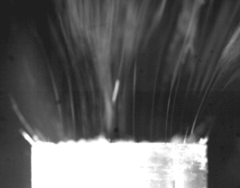
Jet to jet interactions has a major influence on the number of electrospinning jets from an edge or wire. During electrospinning, the Coulomb interaction between the jets will encourage them to be evenly distributed across the spinning edge or wire. As the voltage increases, the number of jets initially increases until repulsive forces between the jets compresses the cone-jets instead of increasing the number of spinning jets. Due to this compression, the self-replenishing flow-rate of the spinning jet remains constant despite increasing voltage. Over a critical voltage, the electrospinning jet may become unstable as the self-replenishing of the spinning cones are choked off by the compression. The number of jets may reduce with a greater inter-jet distance although this has been shown to result in higher flow rate [Roman et al 2013].
Designs:
Spikes / ridges / bowl
Electrical charges tend to concentrate at regions with the highest curvature. Therefore a sharp edge or pointed tip may be used to increase the local charge density for initiation of electrospinning jets. Based on this concept Yarin et al (2004) demonstrated electrospinning from spikes sprouting from a solution reservoir while Lukas et al (2008) used knife edge ridges. Using a bowl with sharp edges and with the solution filled to the brim, Thoppey et al (2011) was able to demonstrate electrospinning jet from the bowl's edge. Since this concept requires the sharp edges to be replenished by the solution reservoir via capillary action, the reservoir level needs to be maintained at a certain level from the tip of the points or edges. Fang et al (2019) did a comparison of the performance of electrospinning using free surface electrospinning, a bowl with oblique edges, a bowl with sharp edges and bubble electrospinning. Their result showed that the setup using the sharp edge bowl electrospinning gave the best results in terms of output and fiber diameter consistency while bubble electrospinning was the worst in both cases. It is surprising that the output from bubble electrospinning is lower than free surface electrospinning. A possible reason could be the constant disruption of the electric field as the bubbles were formed and burst. Instead of having numerous stable spinning jets, the jets in bubble electrospinning have to undergo repeated Taylor Cone formation, jet ejection and termination. The yield from the sharp edge bowl electrospinning in their setup was 20 g/h but bubble electrospinning was just 4.37 g/h. With electrospinning from a bowl, Ahmed et al (2020) investigated the effect of the bowl diameter on the production rate of electrospun fibers. A 25 mm diameter bowl was found to be the optimum size for electrospinning the most polyacrylonitrile (PAN) fibers. With a smaller bowl diameter of 15 mm to 20 mm, the electric field was not uniform due to tio discharge phenomena at the sharp edge of the reservoir causing unstable electrospinning across the surface of the bowl. However, with larger bowl diameters of 30 mm or 40 mm, the electric field distribution is more uniform but the intensity decreases. The reduction in electric field intensity discourages electrospinning jet formation on the free surface and hence most electrospinning jets were only found along the edges where there are charge concentration. With 25 mm diameter bowl, the electric field is uniform across the bowl surface with sufficient electric field intensity for stable and uniform jets across the surface of the bowl. Comparing the yield, the 25 mm diameter bowl has the greatest fiber production.
Having an open solution surface with the electrospinning jets emitting off the sharp edges of the bowl has the issue of solvent evaporation off the solution reservoir surface. This will gradually increase the concentration of the solution to be electrospun. Wei et al (2019) came out with a simple solution to address this problem. Instead of having an exposed surface, the center of the bowl is covered leaving a slit around the edges for the solution exposed for electrospinning. Electrospinning of polyacrylonitrile (PAN} was successfully carried out using this setup with a rotating drum collector overhead. Parameters that were found to increase productivity in this setup include increasing flow rate, applied voltage and reducing collector distance.
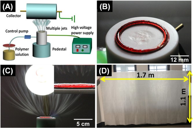
(A) Scheme of a needleless electrospinning apparatus with annular spinneret. (B) The state of spinneret filling with polymer solution. (C) A digital camera image of the multiple jets formed during the electrospinning, insert map: a magnified image of multiple jets formation. (D) The size of nanofiber membrane with annular spinneret. [Wei et al 2019]
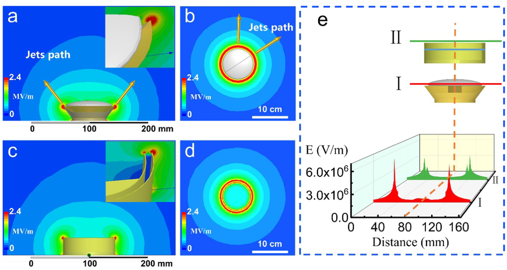
The use of a cover for electrospinning off the edge of a bowl is more beneficial than just reduction of solvent lost through evaporation. By having a cover, the edge of the cover and the bowl effectively forms a slit dispenser. Xiong et al (2021) further refined the slit dispenser design by isolating the charge concentration to just a single edge by using a conductive metal bowl and a polytetrafluoroethylene (PTFE) mushroom-shaped cover to create a slit between the cover and the edge of the bowl. When compared with an uncovered metallic bowl setup, a lower voltage is required for jet initiation for the (PTFE) mushroom-shaped covered bowl. More jets were also formed on the mushroom-shaped covered bowl at the same voltage. The deviation of the electrospun polyacrylonitrile (PAN) fiber diameter was also reduced from a coefficient of variation of 20% to 10% for uncovered and covered bowls respectively. The size of the mushroom cover was also found to influence the charge concentration with a larger mushroom cover resulting in higher charge concentration at the edge of the metallic bowl.
The distribution of electric field intensity of the mushroom-spinneret from (a) the front view and (b) the top view, the inset picture is the corresponding three-dimensional partial enlarged diagram. The distribution of electric field intensity of the metallic slit spinneret from (c) the front view and (d) the top view, the inset picture is the corresponding three-dimensional partial enlarged diagram. (e) Comparison of the distribution of electric field intensity of the mushroom-spinneret and the metallic slit spinneret along the same path in the diameter direction [Xiong et al 2021].
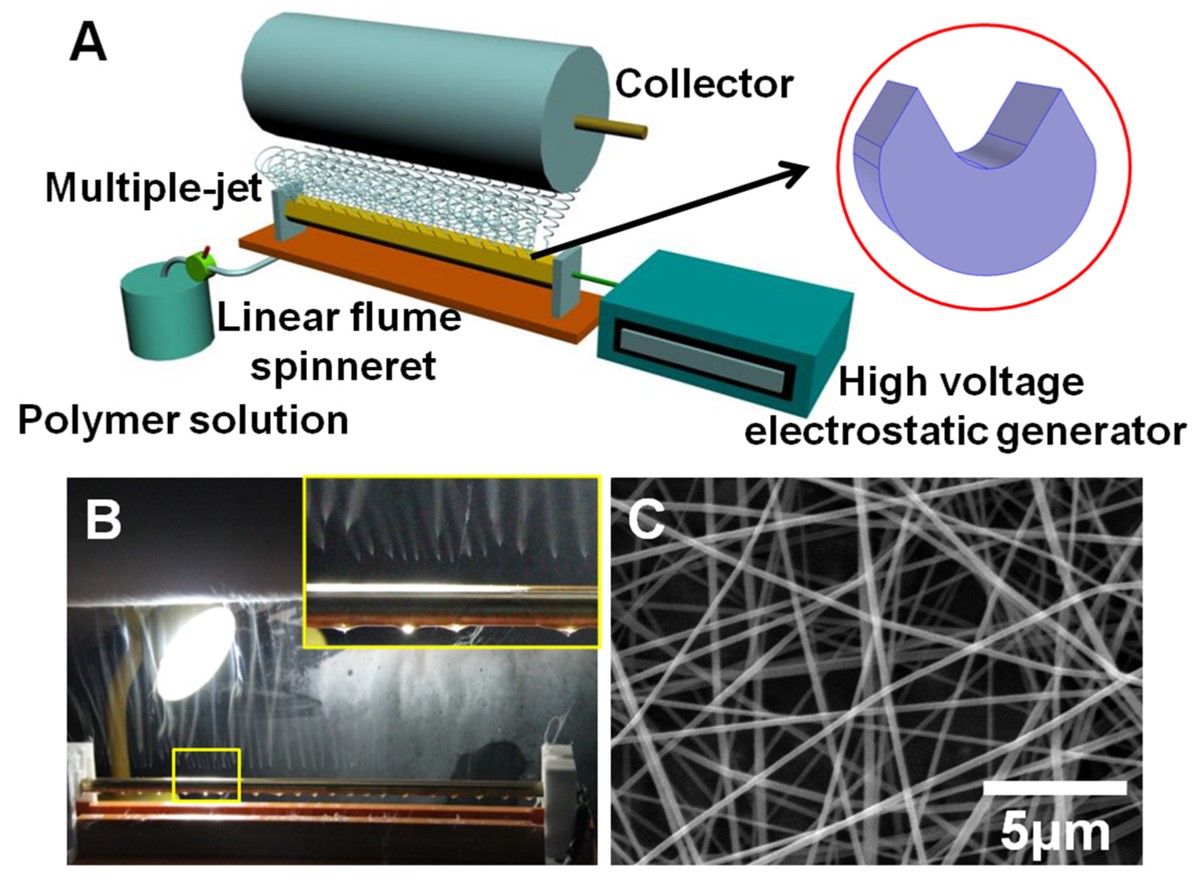
Chen et al (2019) used an inverted bowl spinneret design for melt electrospinning. Unlike solution electrospinning where exposed solvent would vaporise, polymer melt will continue to flow as long as the melting temperature is maintained at the spinneret. Having the bowl inverted meant that the polymer melt would flow down to the edge of the bowl under the pull of gravity. To separate the high voltage for electrospinning and the heating element, the bowl is earthed and the high voltage was applied to the collector instead. The induction of charges on the polymer melt in the electric field would initiate electrospinning. The electrospinning jet was found to self-organise with an inter-jet spacing of 1.1 mm. The bowl spinneret design is a useful concept for containing and providing a sharp edge for electrospinning. However, this configuration may be less suitable for electrospinning in an industrial setup as the supporting substrate for collecting fibers is usually in the form of a rolling sheet. Using the same concept but changing the configuration, Wei et al (2019B) introduced a linear flume spinneret for electrospinning. This retains the sharp edges and a central reservoir of a bowl spinneret design but is configured into a long drain with sharp edges. Polyacrylonitrile (PAN) in N,N-Dimethylformamide (DMF) was used as the model solution for electrospinning. Average diameter of 100 to 200 nm smooth fibers can be produced depending on the concentration, applied voltage and distance between the edge and collector. Along the length of the edge of the spinneret, the density of the jets were found to be 2 to 3 jets/cm. They also found that at higher applied voltage (65 kV), the error of the fiber diameter from the mean reduces. At higher voltage, it may be easier to maintain a steady level of charges for each spinning jet thus leading to a more uniform fiber diameter.
(A) Schematic of the multiple-jet needleless electrospinning setup, the shape of spinneret at the top right corner, (B) photograph of the linear flume spinneret spinning process, enlarged picture of multiple jet formation at the top right corner, (C) SEM image of nanofibers [Wei et al 2019B].
Using MEMS technique Leon et al (2012) constructed one to five conical tips (0.5 - 5 mm height and 50 - 250 µm tip radius) packed into a one-square-centimeter array to increase the production output in electrospinning and to ensure more uniform the fiber diameter. Polyethylene oxide fibers of about 200 nm were fabricated using this setup.
Bringing the size of the solution electrospinning emitters down to the micron scale level has enabled production level that is higher than that from free surface electrospinning. In free surface electrospinning, distribution of local high charge concentration determines the distance between the electrospinning jets and thus the production rate. Presence of spikes or sharp points artificially creates points of charge concentration which favours electrospinning jet formation. Packing larger spikes in higher density may not result in more jet formation. The electric field created by each point interferes with the neighbouring points such that the local potential difference between individual points and the collector is not large enough to cause jet initiation. However, when the spikes or emitters are reduced to the micron level, such fine tip allows greater charge concentration at it tips and this raises the local potential difference between the individual tip and the collector above the background potential difference. With this, Leon (2015) was able to packed hundreds of emitters (tip radii of 250 µm) with spacing at 3 mm apart for electrospinning. Keeping a tip to collector distance close at 3 cm with an applied voltage of 25 kV, they were able to achieve a mass flux of 400 g/hr.m2. This is much higher than free surface electrospinning with mass flux of 100 g/hr.m2. Sharing the same concept of using sharp tips but adopting a different feed solution replenishment method, Moon et al (2017) used a drum with an array of needles as emitters for electrospinning. The drum rotates and dip the needles into a reservoir of solution while electrospinning proceeds at the other side facing a flat collector. In their studies, the arrangement of the needles play an important role in determining the quality of the resultant fibers. Just having the needles in rows and increasing the number of needles only produces fiber aggregates. This phenomenon has been attributed to poor electrical field configuration between the needle tip and the collector. However, rearranging the needles into a helical array significantly improved the electric field line between the emitting needle and the collector. In this arrangement, only a single needle exhibit the strongest electric field line to the collector at any one time with reduced interference from adjacent needles. The use of spikes and needles generally facilitate the formation of Taylor Cone due to charge concentration and hence a lower voltage is needed to initiate electrospinning compared to a flat, free surface electrospinning. In another demonstration of the same concept, Prabu et al (2020) constructed a spinneret made of half-sphere shaped profiled multi-pins. These half-sphere shaped profiled multi-pins help to concentrate charges and make it easier for the solution on its surface to form a sphere-shaped polymer profile on the pin surface. This also meant a lower voltage is needed for electrospinning compared to free surface electrospinning. The multi-pins were loaded with a polymer solution by retracting into a reservoir of the solution and re-surfacing. Electrospinning was carried out with the spinneret at the bottom and the collector above. The setup has successfully electrospun polyvinyl alcohol (PVA) and cellulose acetate (CA). As the volume of the solution available for each round of electrospinning is dependent on the amount of solution coated on the pin, a larger pin diameter would hold more solution on its surface. A diameter of 3.5 mm for the pin was found to be optimal for electrospinning. With a diameter larger than this, multiple electrospinning jets would erupt from each pin surface which is undesirable as this would reduce the uniformity of the fiber produced. A possible drawback of this technique is that over time, the solution may solidify at the tip or edge preventing the polymer solution from rising to the tip/edge and stopping the electrospinning process.
In a modification of the above technique, the spikes or sharp edges may be inverted to point downwards thereby allowing polymer solution injected onto it to flow onto the spikes or edges from above using gravity. This will ensure a constant supply of solution to the tip/edge even though some solution may solidify at the tip. This technique has been successfully demonstrated by Thoppey et al and they have further modified it to include several layers of sharp-edged plates so that the production rate is increased [Thoppey et al 2010]. However, a steady buildup of solidified polymer may "blunt" the tip/edge and reduces the charge concentration effect leading to less effective electrospinning.
Electrospinning using ridges from a solution reservoir [Lukas et al 2008]
Electrospinning from the edge of a bowl [Thoppey et al 2011]
Sharp edge inclined plate to initiate electrospinning [Thoppey et al 2010]
Youtube video
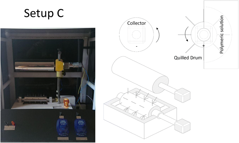
A rotating drum with spikes may be used with a solution reservoir such that the solution on the spikes are replenished each time the spike dipped into the solution reservoir. Tehrani et al (2018) demonstrated such a setup with polyacrylonitrile (PAN) solution. This setup was compared with the output from single and multiple nozzles electrospinning setups. Interestingly, the diameter of the fiber and the standard deviation of the fiber diameter from the spiky drum setup is less than that of the multiple nozzles but greater than a single nozzle setup. However, it is important to note that the arrangement of the spikes on the rotating drum is different from the multi-nozzle setup. The distance between the nozzles were smaller at 25 mm compared to 40 mm between the spikes. Thus, the poorer fiber quality from the multiple nozzles setup may result from their closer proximity and stronger electric field interference.
Electrospinning setup with spikes on a rotating drum [Tehrani et al 2018]
Disk
A slowly rotating disk [Niu et al 2009, Niu et al 2012] that constantly dip into a reservoir of solution eliminates the need for self-replenishment of the solution at the fiber spinning edge. It also ensures a fresh coat of solution on the surface of the disk even though there may be solidified polymer at the underlying layer. However, a steady build up of solidified polymer at the edges over time may lead to a reduction in nanofiber production. This process also has the drawback of having an initial larger volume of solution at the point where the disk emerges from the reservoir which gradually reduces just before the point re-enters into the reservoir. Such uneven distribution of solution for spinning may lead to less uniform fiber diameter.
Rotating disk for initiating electrospinning jet at its edges [Niu et al 2009]
Air jet free surface
Blowing air through subsurface outlets is able to form air cylinders in a free surface solution reservoir which agitate the solution and create interfaces for electrospinning jet formation. Wei et al (2023) demonstrated this concept for electrospinning of polyacrylonitrile solution containing zinc oxide nanoparticles (ZnO). Using a bowl with multiple air outlets just below the solution surface, electrospinning jets were observed to form at the edge of the bowl and air outlets. Comparing electrospun fibers with and without the air flow, the fibers produced from electrospinning without air flow showed agglomeration of nanoparticles while with the airflow, the nanoparticles were evenly distributed. Without airflow, the nanoparticles may settle on the base of the bowl resulting in agglomeration. With airflow circulating the solution, the nanoparticles may remain in suspension throughout the electrospinning duration. However, the airflow needs to be controlled as excessive airflow was found to result in bubbling of the solution and interconnected fibers. This is probably due to fibers being blown to the collector before they are sufficiently dry.
Multiple jets emerging from air jet free surface electrospinning [Wei et al 2023].
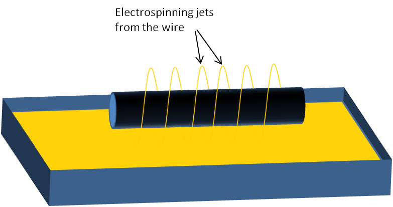
Wire
Electrospinning using spiral wire dipping into solution reservoir [Wang et al 2012]
Electrospinning using parallel wire dipping into solution reservoir [Sambaer et al 2011]
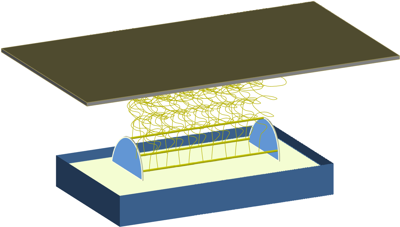
Replicating the purpose of the sharp edge of a disk electrospinning electrode in concentrating the charges on the solution, a thin wire has been shown to be just as capable of electrospinning jet initiation [Wang et al 2012]. A constant supply of solution can be coated on the wire using an applicator or by dipping the wire into a solution reservoir [Wang et al 2012, Sambaer et al 2011]. With a solution reservoir, the wires are rotated and periodically dipped into the solution. The high voltage need not be applied directly to the wire as the surface of the reservoir and the wire will have the same voltage when the solution conductivity is sufficiently high (>1 microS/cm) [Forward et al 2012]. As the wires emerges from the reservoir, droplets start to form on the wire as excess solution drains off by gravity. Above a critical voltage, electrospinning jets erupt independently from the individual droplets and accelerates toward the collector. It was found that with higher voltage, the spacing between the solution droplets reduces and a greater production rate was recorded [Forward et al 2012]. The spinning continues until the solution on the wire depleted or it re-enters the solution reservoir. At sufficiently high voltage, the limiting factor is the rate of solution replenishment on the wires. Therefore, for every rotation speed (which affects the rate of solution replenishment) there will be an optimum applied voltage [Forward et al 2012]. A disadvantage of this method is that a layer of solidified polymer may form on the wire over time.
Youtube video on Spiral wire/Wire Coil electrospinning (Start at 3 min 16 s)
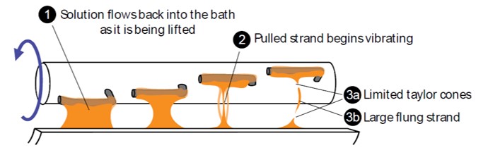
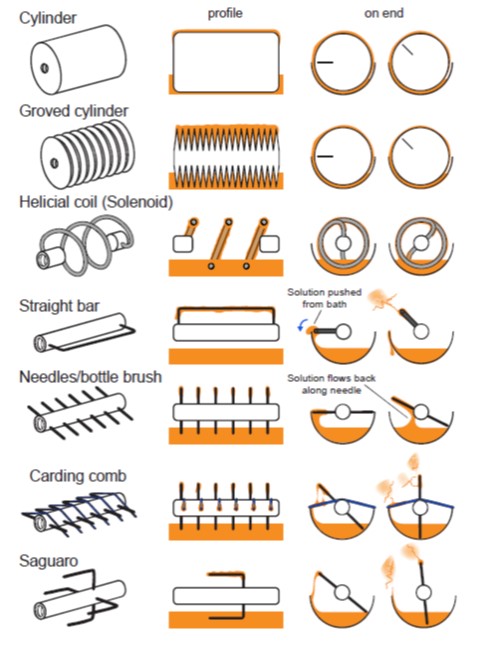
In needleless electrospinning, jet initiation of low viscosity solution is generally easy. However, as viscosity increases, stronger electric field strength is needed. Having small radius surfaces would facilitate electric field concentration and increases local field strength. On a smooth surface rotating drum electrode, protrusions may be added to cause perturbation of the solution and aid jet initiations. Such protrusions have the effect of creating and stretching a thin film of viscous solution. As this film of viscous solution thins and break, Taylor cones form at the broken ends will accelerate towards the collector under the influence of the electric field. These electrospinning jets will stop once the available solution on the protrusion is exhausted. The ability of the solution to form a thin film and stretches is dependent on the design of the protrusions. Comparing a series of protrusion designs, McCarty et al (2019) found that the saguaro electrode protrusion is the most effective in generating electrospinning jets.
A diagram illustrating the assisted formation of Taylor cones from a saguaro electrode. The solution is indicated in orange. (1) As the arms are removed from the bath, the majority of the solution will flow from the arm. (2) The flowing fluid thins and is stretched into a strand, as they are further pulled, they begin to vibrate due to imbalances in the electric field. (3a) After the strand breaks, Taylor cones are formed on the broken ends, and electrospinning jets are observed. (3b) Occasionally, as stretched strand would break, the electric fields would eject large pieces or globs them towards the collector [McCarty et al 2019].
Electrode designs characterized by viscous solutions. The bottom designs were the most successful for spinning viscous solutions [McCarty et al 2019].
To overcome this limitation, a solution applicator may be used to coat the wire with solution. The advantage of this method is that any solidified polymer can be cleaned off the wire through the sliding motion of the applicator. However, since the applicator has to move back and forth to replenish the solution on the wire with the end of the wire nearest to the applicator being the most recently replenished, the rate of solution replenishment and solution expended to form fibers will never be optimum. The length of the wire closest to the applicator will always have excessive solution while the length of the wire at the furthest section will always be devoid of solution.
Dispensing solution over charged wires for electrospinning
A detailed study of the wire electrospinning system using a horizontal applicator on different polymers was carried out by Yalcinkaya et al (2016). 9 types of polymers (polyamide, polyvinylidene fluoride, polyacrylonitrile, polyurethane, polysulfone, chitosan, cellulose acetate, polyvinyl butyral, and polycaprolactone) and their mixtures were electrospun using this system and the morphology of the fibers were examined. For some of the polymers such as polycaprolactone and cellulose acetate, only beaded fibers were produced and mixing with a second polymer is needed to obtain beads-free fibers. Chitosan on its own is not able to form fibers using this electrospinning method and mixing with a second polymer is also necessary. Polysulfone, polyurethane, polyvinylidene fluoride and polyacrylonitrile were able to form smooth fibers.Depending on the applications, having mixed polymers may provide beneficial properties to the resultant fibers. While polycaprolactone and cellulose acetate was able to routinely form smooth fibers using needle electrospinning, further studies will be required to determine the reason for the failure to obtain smooth fiber using wire electrospinning. There are various parameters that can be optimized to increase the productivity of wire electrospinning. A high voltage applied to the wire electrode has been shown to increase the number of electrospinning jets and a reduction of fiber diameter by Prahasti et al (2020) using polyvinylpyrrolidone (PVP) solution. The increase in electrospinning jets with higher voltage can be easily attributed to greater number of solution droplets on the wire electrode reaching the required voltage for jet initiation. The influence of charge concentration on the number of electrospinning jets is also shown by increasing wire electrode diameter. When the diameter of the wire increases, charge concentration reduces and this reduces the number of jets. Fiber diameter was also found to increase probably due to greater availability of solution to be drawn. Similarly, when the distance between the wire and the collector increases, the weakened electric field reduces the number of electrospinning jets.
Youtube video
A hybrid concept where the solution applicator is always moving in a single direction relative to the wire will ensure that an optimum solution application versus applied voltage can be found while reducing any polymer build-up on the wire. A possible setup could be in the form of ring wire electrodes turning in a single direction while passing through a solution applicator. A main drawback of these concpets is that the spinning is constantly disrupted as the solution is being replenished. The number of wires and the spacing between them may also need to be optimized to ensure spinning from all of them.
In an interesting development of electrospinning using wire as spinneret, a twisted wire was used instead of a smooth wire. This is placed vertically such that the feed solution is dispensed at the top and allowed to flow downwards during the electrospinning [Holopainen et al 2015]. Due to the presence of the twist, the electrospinning jets spirals downwards around the wire as the solution flows along the contours of the wire [Holopainen et al 2015]. With a smooth wire, the solution was observed to form large droplets at the top instead of flowing down. A possible explanation could be the textured surface of the twisted wire which reduces contact surface between the solution and the wire surface compared to smooth wire which encourages the droplet to flow down under the force of gravity. As the solution flows from the top, there is an increase in the diameters of the fibers collected from the top to the bottom [Holopainen et al 2015]. This is due to evaporation of the solvent as the solution flows down resulting in relative high concentration at the bottom of the wire [Holopainen et al 2015]. With a wire surface that encourages faster droplet movement, the difference in concentration at the top and the bottom of the wire can be reduced. This may also encourages higher productivity as more solution can be released from the top without causing it to accumulate.
Based on the same concept, multiple vertical rods have been used for solution to flow under the force of gravity and charged to initiate electrospinning [Shin et al 2015a, 2015b]. Since the rods are being charged with the same voltage and polarity, the electrospinning jets will repel one another and collect on the grounded plates instead. A higher productivity can be expected with more rods to dispense the solution. The production rate was found to increase with increasing electric field strength either by increasing the voltage applied or reducing the gap between the rods and collector [Shin et al 2015b].
A limitation using solution flowing down vertical wire/rod for electrospinning is that there will be coating of solution residues on its surface due to evaporation which will retard the downward flow of subsequent solution and eventually stopping the flow altogether [Holopainen et al 2015]. This limitation may be overcome by future development of cleaning system during the electrospinning process [Holopainen et al 2015]. Another constrain is the length of the wire which in turn affects the width of the membrane that can be fabricated. With a longer the wire and subsequent greater traveling time of the solution from the top to the bottom, more significant increase in the solution concentration due to evaporation will result in greater increase in fiber diameter. Notable advantage of this system is its lack of mechanical parts, little wastage of solution and high productivity.
Published date: 04 August 2012
Last updated: 17 October 2023
Ahmed A, Yi Jn, Lan Xu, Khan F. High-throughput free surface electrospinning using solution reservoirs with different radii and its preparation mechanism study. Journal of Materials Research and Technology 2020; 9: 9059.
Open Access
Chen M, Zhang Y, Li H, Li X, Ding Y, Mahmoud M B, Yang W. An example of industrialization of melt electrospinning: Polymer melt differential electrospinning. Advanced Industrial and Engineering Polymer Research 2019 Article in press.
Open Access
Fang Y, Xu L. Four self-made free surface electrospinning devices for high-throughput preparation of high-quality nanofibers. Beilstein J. Nanotechnol. 2019; 10: 2261.
Open Access
Forward K M, Rutledge G C. Free surface electrospinning from a wire electrode. Chemical Engineering Journal 2012; 183: 492.
Holopainen J, Penttinen T, Santala E, Ritala M. Needleless electrospinning with twisted wire spinneret. Nanotechnology 2015; 26: 025301.
Leon P P. Parallel Nano-Manufacturing via Electro-Hydrodynamic Jetting from Externally-Fed Emitter Arrays. MSc Thesis. Massachusetts Institute of Technology 2015.
Open Access
Leon P J P, Hill F A, Velasquez-Garcia L F. Batch-microfabricated arrays of electrospinning emitters for high throughput generation of nanofibers. PowerMEMS 2012, Atlanta, GA, USA, December 2-5, 2012.
Lukas D, Sarkar A, Pokorny P. (2008) Self-organization of jets in electrospinning from free liquid surface: A generalized approach J. Appl Phys. 103. 084309.
McCarty R J, Giapis K P. An Adaptable Device for Scalable Electrospinning of Low- and High-Viscosity Solutions. Instruments 2019; 3: 37.
Open Access
Moon S, Gil M, Lee K J. Syringeless Electrospinning toward Versatile Fabrication of Nanofiber Web. Scientific Reports 2017; 7: 41424.
Open Access
Niu H, Lin T, Wang X. (2009) Needleless electrospinning. I. A comparison of cylinder and disk nozzles. J. Appl. Polym Sci. 114 pp 3524
Prabu G T V, Dhurai B. A Novel Profiled Multi-Pin Electrospinning System for Nanofiber Production and Encapsulation of Nanoparticles into Nanofibers. Scientific Reports 2020; 10: 4302.
Open Access
Prahasti G, Zulfi A, Munir M M. Needleless electrospinning system with wire spinneret: an alternative way to control morphology, size, and productivity of nanofibers. Nano Express 2020; 1: 010046.
Open Access
Sambaer W, Zatloukal M, Kimmer D. 3D modeling of filtration process via polyurethane nanofiber based nonwoven filters prepared by electrospinning process. Chemical Engineering Science 2011; 66: 613.
Shin H U, Li Y, Paynter A, Nartetamrongsutt K, Chase G G.Vertical rod method for electrospinning polymer fibers. Polymer 2015; 65: 26.
Shin H U, Li Y, Paynter A, Nartetamrongsutt K, Chase G G. Microscopy analysis and production rate data for Needleless vertical rods electrospinning parameters. Data In Brief 2015 Article in PressOpen Access
Roman M P, Thoppey N M, Gorga R E, Bochinski J R, Clarke L I. Maximizing Spontaneous Jet Density and Nanofiber Quality in Unconfined Electrospinning: The Role of Interjet Interactions. Macromolecules 2013; 46: 7352.
Tehrani P R, Hadjianfar M, Afrashi M, Semnani D. An investigation on quilled nozzle-less electrospinning in comparison with conventional methods for producing PAN nanofibers. Fashion and Textiles 2018; 5: 24.
Open Access
Thoppey N M, Bochinski J R, Clarke L I, Gorga R E. Unconfined fluid electrospun into high quality nanofibers from a plate edge. Polymer 2010; 51: 4928.
Thoppey N M, Bochinski J R, Clarke L I, Gorga (2011) Edge electrospinning for high throughput production of quality nanofibers. Nanotechnology 22, 345301.
Wang X, Niu H, Wang X, Lin T (2012) Needleless Electrospinning of Uniform Nanofibers Using Spiral Coil Spinnerets. J. Nanomat. 2012, 785920
Open Access
Wei L, Liu C K, Mao X, Dong J, Fan W, Zhi C, Qin X H, Sun R J. Multiple-Jet Needleless Electrospinning Approach via a Linear Flume Spinneret. Polymers 2019B; 11(12): 2052.
Open Access
Wei L, Sun R, Liu C, Xiong J, Qin X. Mass production of nanofibers from needleless electrospinning by a novel annular spinneret. Materials & Design 2019; 179: 107885.
Open Access
Wei D, Ye C, Ahmed A, Lan Xu. Batch preparation of nanofibers containing nanoparticles by an electrospinning device with multiple air inlets. Beilstein J. Nanotechnol. 2023; 14: 141.
Open Access
Xiong J, Liu Y, Li A, Wei L, Wang L, Qin X, Yu J. Mass production of high-quality nanofibers via constructing pre-Taylor cones with high curvature on needleless electrospinning. Materials & Design 2021; 197: 109247.
Open Access
Yalcinkaya F. Preparation of Various Nanofiber Layers Using Wire Electrospinning System. Arabian Journal of Chemistry 2016 Article in pressOpen Access
Yarin A L, Zussman E (2004) Upward needleless electrospinning of multiple nanofibers Polymer 45 pp 2977.