Many investigations on electrospinning mass production dispenser revolve around needles and needleless design. With needle, it offers the advantage of charge concentration at the needle tip which facilitates jet initiation. However, its main weakness is that it imposes greater restriction in the number of jets initiation. For needless design, there is much less restriction on the quantity of electrospinning jet initiation but this is at the expense of high voltage application for jet initiation. At the middle ground between these two is the slit dispenser design. The main characteristic of this design is that it contains a narrow slit which the solution is dispensed. The narrow slit facilitates controlled feeding of the solution and charge concentration. Another advantage of this design is that monitoring of the production process is simpler.
Electrospinning jets are emitted in a line along the slit and the productivity can be monitored by the spacing between the adjacent jets or by the number of jets using imaging technique. Kula et al (2014) showed that jets tend to distribute evenly along the length of the slit thus providing a consistent intra-jet distance at a given voltage. With increasing voltage, the intra-jet distances are reduced which means higher number of jets are emitted in the given length.
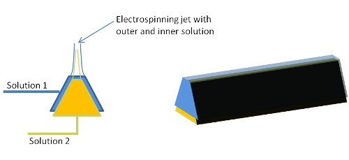
This design has been modified to enable production of core-shell fibers. As shown in the schematic, it comprises of two triangular troughs with an outer and inner slit [Yan et al 2012]. During jet initiation, the drawing of the solution from the outer trough will exert a shearing force on the inner solution thereby drawing the inner solution concurrently. In their experiment, it was shown that a sheath solution with a higher viscosity than the core solution is better in maintaining a distinct core-sheath fiber.
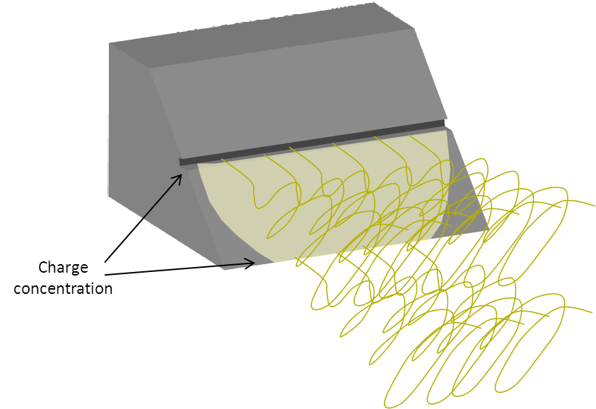
In a combination of needleless design concepts, Ucar et al (2013) constructed a solution dispenser with a slit and a sharp edge. This design contains two regions of charge concentration, one at the slit and the other on the sharp edge at the end of a plane surface. This hybrid setup enables electrospinning jet to erupt from the slit and where there is excessive solution flowing down a plane surface, the sharp edge at the end of the plane surface will also enables jet initiation. This design was able to produce homogeneous sheet of nanofibers compared to non-homogeneous coating from electrospinning using multiple nozzles. This design is also effective in preventing clogging of the solution dispensing head during electrospinning.
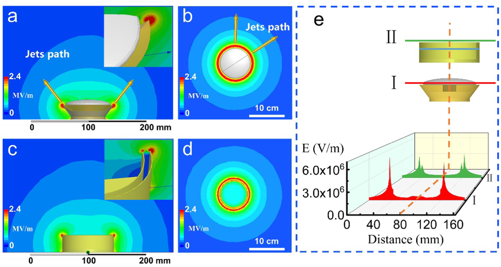
A limitation of many needleless mass production electrospinning is the quality of the fiber output. In most cases, the fiber diameter distribution is large which may be attributed to the difficulty of maintaining the same voltage for each erupted jet due to local charge concentration. A slit dispenser design helps to reduce the inconsistency of local charges by limiting the jet output region and deliberate concentrating of the charges. Xiong et al (2021) further refined the slit dispenser design by isolating the charge concentration to just a single edge. The setup uses a conductive metal bowl and a polytetrafluoroethylene (PTFE) mushroom-shaped cover to create a slit between the cover and the edge of the bowl. When compared with an uncovered metallic bowl setup, a lower voltage is required for jet initiation for the (PTFE) mushroom-shaped covered bowl. More jets were also formed on the mushroom-shaped covered bowl at the same voltage. The deviation of the electrospun polyacrylonitrile (PAN) fiber diameter was also reduced from a coefficient of variation of 20% to 10% for uncovered and covered bowls respectively. The size of the mushroom cover was also found to influence the charge concentration with a larger mushroom cover resulting in higher charge concentration at the edge of the metallic bowl.
Published date: 16 Sep 2014
Last updated: 13 April 2021
▼ Reference
-
Kula J, Linka A, Tunak M, Lukas D. Image analysis of jet structure on electrospinning from free liquid surface. Applied Physics Letters 2014; 104: 243114.
-
Ucar N, Ucar M, Kizildag N. Design of a novel nozzle prototype for increased productivity and improved coating quality during electrospinning. Tekstil ve Konfeksiyon 2013; 23: 199.
-
Xiong J, Liu Y, Li A, Wei L, Wang L, Qin X, Yu J. Mass production of high-quality nanofibers via constructing pre-Taylor cones with high curvature on needleless electrospinning. Materials & Design 2021; 197: 109247.
Open Access
-
Yan X, Pham Q, Marini J, Mulligan R, Sharma U, Brenner M, Rutledge G, Freyman T. High-throughput needleless electrospinning of Core-Sheath Fibers. The Fiber Society 2012 Fall Meeting. Pp. 96 Open Access
▲ Close list