Home | About | Contact


Supported Electrospun 3D structure

Fibers, with their large length to diameter aspect ratio and low stiffness, are individually too weak to be self supporting. Therefore, 3D forms of electrospun fibers are made out of bundles of fibers or are supported by other means. In this article, we will describe how electrospun 3D structures have been constructed with the assistance of other supporting material or structure.

A supporting structure may be used to hold the electrospun fibers in a 3D spatial form for its application. Zhou et al (2018) used a trough collector comprising of a flat base and slanted walls to gather electrospun fibers along the depth of the collector. The collected fibers were aligned wall to wall to form a 3D structure supported by the walls. Fibroblasts cultured on this supported structure were found to be distributed throughout the fibrous matrix and aligned according to the fiber orientation. In this case, the supporting structure purpose is to hold the electrospun fibers in a 3D spatial form only while allowing the cultured cells to populate the scaffold. In most other forms, the supporting material is combined with the electrospun fibers as a whole scaffold.


Trough collector setup to support electrospun 3D structure [Zhou et al 2018].

3D printing has gained popularity due to the ability to create customised structures from bottom up. However, it is difficult to create nano-struts using this method. To improve cell adhesion and proliferation on the scaffold constructed using 3D printing or rapid prototyping technique, electrospun nanofibers have been incorporated into the scaffold during construction. The 3D plotting technique where molten polymer is used to eject strands of microfibers to build up a scaffold is commonly used in combination with electrospinning. When a deck of microfibers is built, nanofibers are deposited on the surface before the next layer of microfibers is added on. This way, a whole scaffold consisting of microfibers and nanofibers is constructed.

Nanofiber-RP scaffold
Combining electrospinning with Rapid Prototyping process

In certain cases, the supporting material may gain mechanical strength from having electrospun fibers. Hydrogel can be made easily into a 3D block. However, it lacks mechanical strength since it is mostly filled with water. Incorporation of nanofibers into hydrogel has been shown to improve the mechanical properties of the hydrogel [Kai et al 2012; Visser et al 2015; Liu et al 2014] and the presence of nanofibers may also potentially improve or influence cell activity in the resultant composite [Yang et al 2011]. To create a uniform composite of electrospun fibers and hydrogel, electrospinning and electrospraying of hydrogel can be carried out simultaneously. This will progressively build up a hybrid structure [Ekaputra et al 2008].

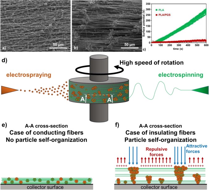
Particles and microparticles have been loaded into electrospun fibers and removed to increase the pore size of the scaffold. However, the particles may also be retained to function as supporting structures to increase the separations between the electrospun fibers. Flaig et al (2024) constructed a 3D aligned electrospun poly(lactic acid) (PLA) fiber scaffold with electrosprayed poly(glycerol sebacate) prepolymer (pPGS)/hydroxypropyl-β-cyclodextrin (HPβCD) microparticles as the supporting structures between PLA fiber layers. Interestingly, with PLA fibers the pPGS/HPβCD microparticles self-organise under the influence of residual charges to form columns on the fiber layer surface. However, on electrospun pPGS/PLA fibers, the pPGS/HPβCD microparticles were evenly distributed. Such differences in the organisation of the microparticles have been attributed to the non-conductive nature of PLA which led to greater retention of residual charges that direct the electrosprayed pPGS/HPβCD microparticles. Electrospun pPGS/PLA fibers showed greater conductivity and this favoured quick discharge and hence the low level of residual charges encourages a more uniform microparticles distribution. For the next layer of electrospun fibers over the microparticles, PLA fibers showed much better alignment compared to pPGS/PLA fibers. The presence of pPGS/HPβCD microparticles on PLA fibers layer created a lower charge zone due to the dissipation of charges by the microparticles while regions away from the particles showed high retained charges. The distribution of charged and uncharged zones encourages the fibers to align in a more orderly manner.


Top surface of samples elaborated from 3 superimposed bilayers, each corresponding to a layer of nanofibers (PLA or PLA/PGS) deposited during 2 min followed by 1 min of electrospraying pPGS/HP?CD microparticles. a) Scaffold with PLA/PGS nanofibers. b) Scaffold with PLA nanofibers. c) Surface potential measured during 10 min of electrospinning alone (i.e. without electrospraying) of PLA (green upper curve) and PLA/PGS (red lower curve). d) Scheme of the electrospraying set-up. e) Scheme of the deposited fibers and particles in the case of conducting fibers (e.g. PLA/PGS). f) Scheme of the deposited fibers and particles in the case of insulating fibers (e.g. PLA) [Flaig et al 2024].

Published date: 08 January 2019
Last updated: 21 April 2026

Comments
[+]


Google Ad.