Home | About | Contact


Hybrid electrospun fibers with surface structures and projections


Examples of surface projections from the surface of electrospun fibers.

Surface structures on electrospun fibers may come in the form of nanoparticles, rods or spikes. Presence of such structures further increase the surface area for interaction with the environment while remaining adhered to the macrostructure. Functional nano-structures that are attached to the surface of electrospun fibers offer several advantages over having them within the fiber matrix. An obvious advantage of having them exposed on the surface is it allows direct contact with the reactants. Virovska et al (2014) demonstrated with ZnO nanoparticles that are embedded within electrospun poly(l-lactide) (PLA) nanofiber matrix through blending and electrosprayed on the surface of PLA nanofiber that the composite with ZnO nanoparticles on the surface of PLA nanofibers showed better photocatalytic and antibacterial activity. The quantity of nanoparticles loading on the structure may also be increased without causing deterioration in the fiber quality. There are a few methods of forming surface structures such as physical adhesion, chemical reaction and molecular self-organization.


Physical Adhesion

Surface adhesion may come from secondary forces such as hydrogen bonding, van der Waals forces or through partial melting of deposited particles on the nanofiber surface. The simplest form of coating involves dipping the electrospun fibers into a solution or suspension of conductive material such that the conductive material adheres to the surface of the fibers. Kang et al [2007] dipped electrospun silk membrane into a suspension of multi-walled carbon nanotube (MWCNT) in water containing Triton X-100. The MWCNT was found to adhere to the surface of the silk nanofiber and remained adhered after washing with de-ionized water. Instead of having a two steps process for adhering nano-particles onto the surface of nanofibers, Zheng et al (2014) electrospun cellulose directly into an aqueous suspension of magnesium hydroxide nanoparticles. As the cellulose fibers are formed in the aqueous suspension, the magnesium hydroxide nanoparticles adhered on the surface of the fibers. An advantage of this method is that the distribution of the nanoparticles across the bulk nanofibrous structure is likely to be more uniform than having the coating as a separate process. Kang et al [2012] demonstrated the use of hydrogen bonding to coat nanofiber with egg-shell membrane. Electrospinning was carried out to form nanofibers from caprolactone and catechin blend. When submerged in egg-shell membrane solution, catechin diffuses to the surface of the fiber and activates the precipitation of egg-shell membrane due to the formation of hydrogen bonding between them.

Simultaneous electrospinning and electrospraying may be used to incorporate functional nanoparticles on the surface of the nanofibers within the membrane. Alternatively, an ultrasonic atomizer [Dong et al 2013], airbrush or other spraying device may be used in place of electrospraying. Spraying may be directed at the electrospinning jet such that the particles are attached to the fiber surface prior to deposition on the mat [Xuyen et al 2009] or at the opposite side of a rotating collector [Jaworek et al 2009]. Almost any kind of nanoparticles can be incorporated on the surface the nanofibers using this method. TiO2, MgO and Al2O3 nanoparticles have been coated uniformly across the thickness of the membrane using simultaneous electrospinning and electrospraying [Jaworek et al 2009]. Zhang et al (2013) tested the stability of the TiO2 particles on nylon-6 membrane by sonication in ultrasonic bath for a few minutes. The internal microstructure of the membrane remains unchanged and this demonstrated the adhesion stability of the particles to the membrane. Post spinning process such as heat treatment may be required to ensure better bonding or fusion between the particles and the fibers.


Surface Precipitation

This technique usually requires the nanofibers to contain active groups which encourage precipitation of crystals on its surface. In the absence of active groups, precipitation either does not occur or results in very few crystals deposition. The amount of crystals deposited on the nanofiber surface is typically controlled by varying the concentration of the precipitate solution or the length of immersion in the solution.

mineralized electrospun fibers
Mineralized nanofibrous scaffold

In the construction of mineralized scaffold for bone regeneration, nanofibers are often coated with calcium phosphate nanoparticles to enhance biocompatibility. While nanoparticles may be able to adhere on the surface of the nanofibers without any reactive sites, materials containing functional groups such as carboxyl groups are often used or blended into the core material for better enrichment of Ca2+ ions during the mineralization process. The three most commonly used methods of mineralization is dipping the scaffold in concentrated simulated body fluid (SBF), dipping in supersaturated calcification solution and alternate soaking method. Of these three methods, the alternate soaking method is probably the fastest in encouraging the formation of calcium phosphate on the surface of the fibers [Meng et al 2013].

Other minerals may also be formed nanofiber surfaces for other applications. Jia et al (2014) coated polyamide-6 with Mg(OH)2 nanoparticles for the removal of Cr(VI) in water. Polyamide-6 contains a functional group (>C=O) where Mg2+ adheres to. Precipitation of Mg2+ on the surface of electrospun polyamide-6 nanofibers in a solution can be encouraged by addition of a weak base, NH3. H2O, to lower the degree of supersaturation and at temperature of 40°C.


Catalyst

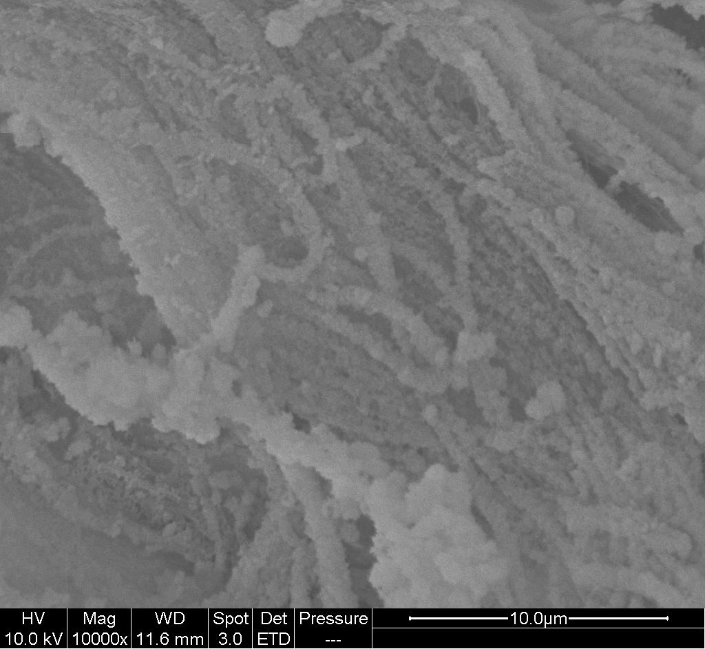
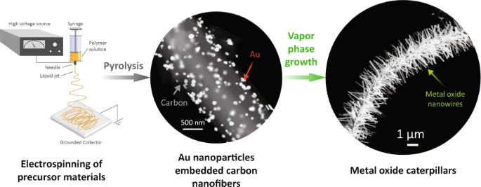
Nanoparticles can be easily incorporated within electrospun fibers through blending which can later be used as catalyst to encourage growth of nanorods from its surface. Lai et al (2008) constructed carbon nanofibers containing Pd(Ac) by carbonizing polyacrylonitrile (PAN). The Pd nanoparticles function as catalysts to facilitate growth of carbon nanotubes and carbon nano-ribbons from the surface of the carbon nanofibers. Vapor phase transport (VPT) uses catalysts embedded on a substrate to initiate and grow nanostructures off the substrate. Islam et al (2022) electrospin AuCl3/PAN nanofibres followed by carbonization to form Au nanoparticles (AuNPs)-decorated carbon nanofibres. The presence of AuNPs function as the catalyst for VPT growth in a furnace. A mixture of graphite powder and ZnO powder was used as the source for VPT growth in a furnace. The growth in the diameter and length of the nanostructures increases linearly with the furnace temperature. It is only at temperature pf 1000 °C that microstructure starts to project from the nanofibers surface with gold nanoparticle droplets at the tip of many ZnO projections. In VPT, it is the metal vapor atoms that binds onto the catalyst. Therefore, higher temperature would increase the formation and movement of the metal vapor atoms and facilitate crystal growth. The same VPT condition yielded similar projections from In2O3 and SnO2.


Illustration of the fabrication process with electrospinning, carbonization to obtain carbon fibers with surface catalyst and vapor phase growth of metal oxide nanowires around the nanofibres [Islam et al 2022].


Controlled Crystal Growth

Given the right condition, crystals can be encouraged to grow on nanofibers to form projections. This can be applied to both organic and inorganic materials although the conditions used are different. Ochanda et al (2012) uses TiO2 nanofibers from electrospun polyvinyl pyrrolidone (PVP) and titanium isopropoxide as the substrate for growing TiO2 nanorods using a solvothermal process in NaOH. Meng et al (2011) also used TiO2 nanofibers as the substrate for growing TiO2 nanorods from its surface. The anatase nanofibers were dipped in titanium isopropoxide solution and heated to a range of temperature from 130 °C to 170 °C and at residence times from 1 h to 3 h. Distinct nano-rods made out of rutile phase were formed uniformly along the nanofibers and projecting at right angles to the surface of the fibers. Lu et al (2019) used a hydrothermal process to grow ZnO nanorod projections from electrospun polyimide (PI) and polyimide/Ag fibers. Electrospun polyimide and polyimide/Ag fibers were first soaked in Zn(Ac)2·2H2O/ethanol solution followed by heat treatment to form ZnO seed layer on the fibers. An aqueous solution of Zn(NO3)2·6H2O and hexamethylenetetramine were prepared for the hydrothermal process to grow ZnO projections. After immersing the seeded fibers in the aqueous solution for 6h at 85°C, the PI and PI/Ag were coated with ZnO nanorod. PI/Ag/ZnO nanorods may undergo further UV irradiation to obtain Ag nanoparticles followed by immersion in AgNO3 solution and UV irradiation.


SEM micrographs of TiO2: (a) pure electrospun TiO2, (b) 1 h solvothermal treatment showing TiO2 particle nucleation on nanofibre surface. (C) Hierarchical TiO2 after solvothermal treatment for 6 h showing the onset of nano-scale flower-like coverage of nanofibre surface, (D) for 12 h showing nano-scale flower-like nanostructures completely covering the nanofibre surface. (E) Expanded view of (D) showing the nanorod network, (F) TEM micrograph shows the microstructure of the nanorods. [Ochanda F O, Rajukada S, Barnett M R. Controlled Synthesis of TiO2 Hierarchical Nanofibre Structures via Electrospinning and Solvothermal Processes: Photocatalytic Activity for Degradation of Methylene Blue. Nanomater. Nanotechnol. 2012; 2: 1. CC by 2.0]

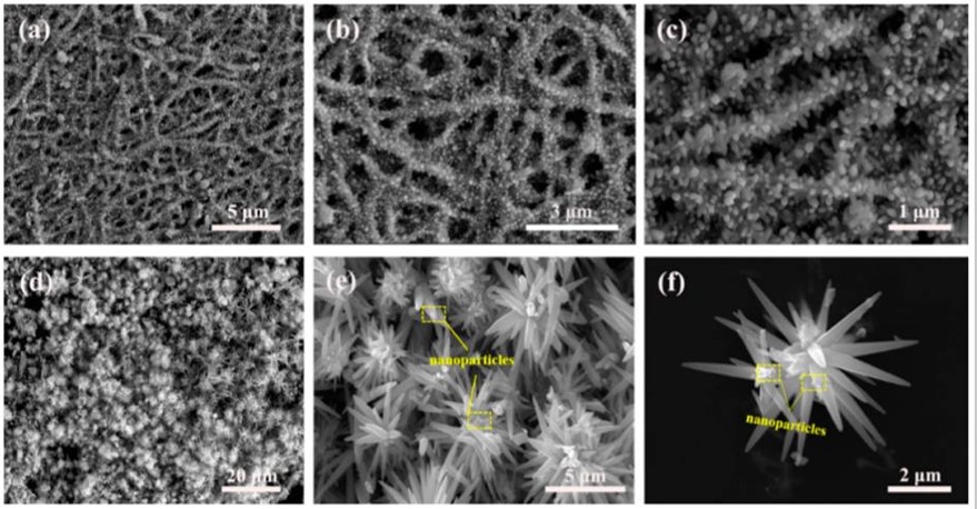
TiO2 nanofibers has also been shown to be able to encourage projections of vanadium oxide from its surface. Similar to the methods described earlier, TiO2 nanofibers were immersed in vanadium sol and then taken out to dry at 170 °C. After repeating the process of immersion and drying three times, the resultant composite structure was annealed at 550 °C. During annealing, the vanadium oxide grows along the radial direction of the nanofibers to form distinct spikes along the nanofiber length [Zhao et al 2014]. Growth of projections from electrospun fibers using hydrothermal process may also be used for the production of single material hierarchically structured fibers. Fan et al (2019) produced electrospun ZnO nanofibers with two different types of surface projections. ZnO nanofibers were first produced by annealing of electrospun Zn(CH3COO)2·2H2O/polyvinylpyrrolidone (PVP) fibers. A reaction solution was prepared by mixing hexamethylenetetramine (HMTA) and zinc nitrate hexahydrate (Zn(NO3)2·6H2O) followed by the addition of ZnO. Hydrothermal reaction of this mixture produces fire cracker like surface. When the ZnO nanofibers were sonicated prior to hydrothermal treatment, flower like projections were produced. This is because ZnO nanoparticles generated from the ultrasonication acts as nucleus for the growth of rod projections hence forming flower like structure.


SEM images of as-prepared samples: (a) ZnO with fire cracker like surface in low magnification, (b,c) ZnO with fire cracker like surface at high magnification, (d) ZnO with flower like projections in low magnification and (e,f) ZnO with flower like projections at high magnification [Fan et al 2019].

Selenization has also been found to encourage growth surface projections from electrospun Fe(acac)3-polyacrylonitrile (PAN) composite fibers. Electrospun Fe(acac)3-PAN composite fibers and Se metal powder was place together in a quartz tube reactor for the selenization process. The selenization temperature was found to have a significant impact on the morphology of the resultant fibers. At 500 °C, rod-like FeSe projections were found on the fiber surface. Increasing the selenization temperature to 1000 °C transform the rod-like projections into spherical nanocrystals.

Controlled polymer crystallization is a process where polymer crystals on the nanofiber are grown into projections from the nanofiber surface. Wang et al (2008) successfully demonstrated this method using polyethylene oxide. Following electrospinning of polyethylene oxide(PEO) nanofibers, the nanofibers were incubated in dilute PEO in dimethyl formamide (DMF) for about an hour. After drying, a uniform distribution of PEO single crystals can be seen like flanges distributed periodically around the nanofiber length.


Molecular Self-Organization

Molecular self-organization may be induced on the nanofibers under the right stimulus such as annealing. Meng et al (2011) showed that with electrospun polyarylene ether nitriles (PEN) and iron phthalocyanine polymer (FePc) blend, the more mobile FePc will migrate to the surface of the nanofibers. Following heat treatment, FePc "thorns" were found to project from the surface of the nanofibers. The length of the "thorns" can be varied by controlling the heating temperature and duration.


Published date: 19 May 2015
Last updated: 10 January 2023

Comments
[+]


Google Ad.