Collection and tensile testing of single strand electrospun nanofiber
This work by ElectrospinTech is licensed under a Creative Commons Attribution 3.0 Unported License.
Purpose
This SOP describes the method of collection and testing of a single strand electrospun fiber. Two methods of fiber collection will be described in this SOP. One for the collection of as-spun fiber and another for the collection of drawn fiber. Method of preparing the sample and test procedure will be described here.
WARNING: High voltage used in electrospinning can result in serious injury if proper safety precautions are not taken.
|
Disclaimer Any instruments and materials mentioned in this standard is for reference only. Electrospintech does not guarantee its availability or quality. This standard did not undergo formal peer review process and is for reference only. This standard does not address all safety and health issues regarding the performance of the experiment and/or the end product if any. It is the responsibility of the user to establish appropriate controls, safety and health practices. Local regulatory controls and limitation shall be addressed by the users of this standard prior to its use. |
1. Introduction
In most applications, nanofiber is not used in isolation but as a bundle or mesh. However, since a nanofiber is the building block, it is useful to understand its mechanical properties. There are several challenges in measuring the mechanical properties of single strand nanofiber. Firstly, the fiber is very weak and may break in the nano-newton range therefore the load transducer must be sufficiently sensitive. Secondly, getting the fiber into position is also a challenge as it is unable to withstand physical handling. Finally, observation of the fiber also becomes increasingly difficult under an optical microscope and direct measurement of the sample to be tested is almost impossible.
2. Equipment and consumables
2.1 Electrospinning apparatus
The electrospinning setup may be procured (See List of Electrospinning setup and product suppliers) or self-assembled (See ES1001).
2.2 Collector
2.2.1 As-spun fiber collector
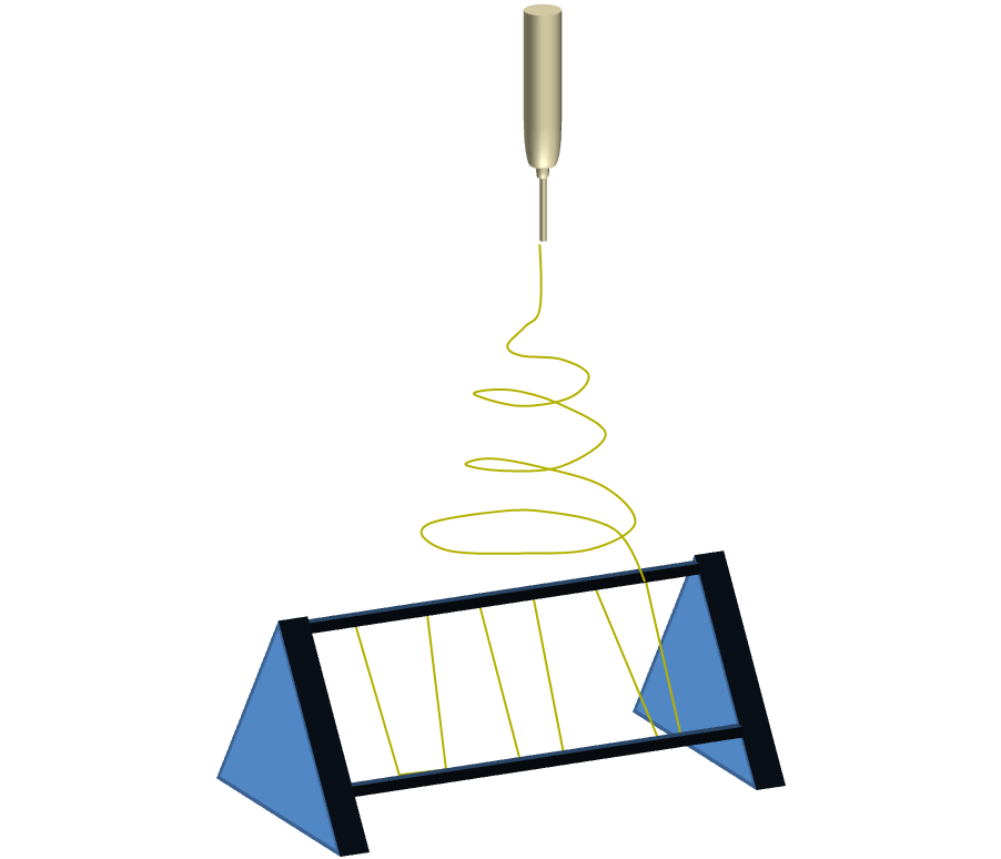
For the collection of as-spun fibers, a standing collector frame may be used (See figure 1). The parallel horizontal bars should be constructed of metal and electrically earthed.
|
| Figure 1. Electrospinning collector frame for collecting as-spun fibers |
The distance between the parallel horizontal bar should be about 40 mm or more depending on the gauge length used.
2.2.2 Drawn fiber collector
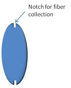
A rotating disk modified to include with sectional gaps of 40 mm or more (depending of gauge length used) will be required. See figure 2.
|
| Figure 2. Modified disk collector with a notch or gap (40 mm width) for collecting drawn fibers |
2.3 Bench-top halogen lamp and a black board
The halogen lamp is used to illuminate the collected fibers against the black background (black board). This is to facilitate picking a single strand of fiber off the collector using the frame.
2.4 Bench top magnifying glass or optical stereomicroscope (optional)
For observing and isolating fiber
2.5 Scanning electron microscope (SEM)
2.6 Tensile tester with load cell of less than 1 N
Eg. Nano tensile tester from NanoBIonix, MTS with load resolution of 50 nN and extension of 35 nm.
Note. See Appendix C for examples of breaking load for single strand electrospun fiber
2.7 Material
2.7.1 Electrospinning solution and general consumables associate with it
2.7.2 Testing Window Frame (paper or thin plastic sheet)
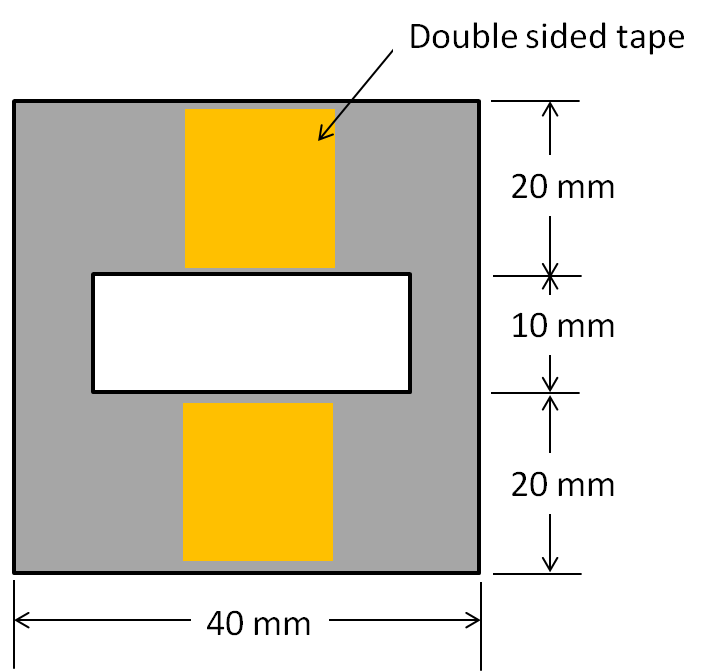
The dimension of the window frame is shown in figure 3. Double-sided tapes are used to secure the fiber onto the frame.
|
| Figure 3. Window frame made of paper board or plastic sheet for gathering single strand fiber for tensile testing |
2.7.3 Small diameter rod eg. Tooth pick, needle
To isolate a single strand fiber
3. Procedures
3.1 Fiber collection
3.1.1 As-spun fiber
Place the collector in position (remember to electrically earth the collector)
Switch on the high voltage power supply to commence electrospinning.
3.1.2 Drawn fiber collector
Switch on the rotating disk.
After the rotating disk has reached the desired rotation speed, switch on the high voltage power supply to commence electrospinning.
3.1.3 Collection of single fiber strand
Electrospin for about 10 to 20 s and stop the spinning process.
Hold the standing collector frame close to the halogen lamp and look out for fibers against a dark background.
Select a single fiber strand that is almost orthogonal to the edge and use the small-diameter rod to remove the other fiber strands.
Use the testing window frame (with double sided tapes) to pick up the single strand of fiber, making sure that the fiber is perpendicular to the edge of the frame and is secured on the double sided tapes. A drop of super glue (ethyl-2-cyanoacrylate) may be applied on the fiber to secure it to the frame.
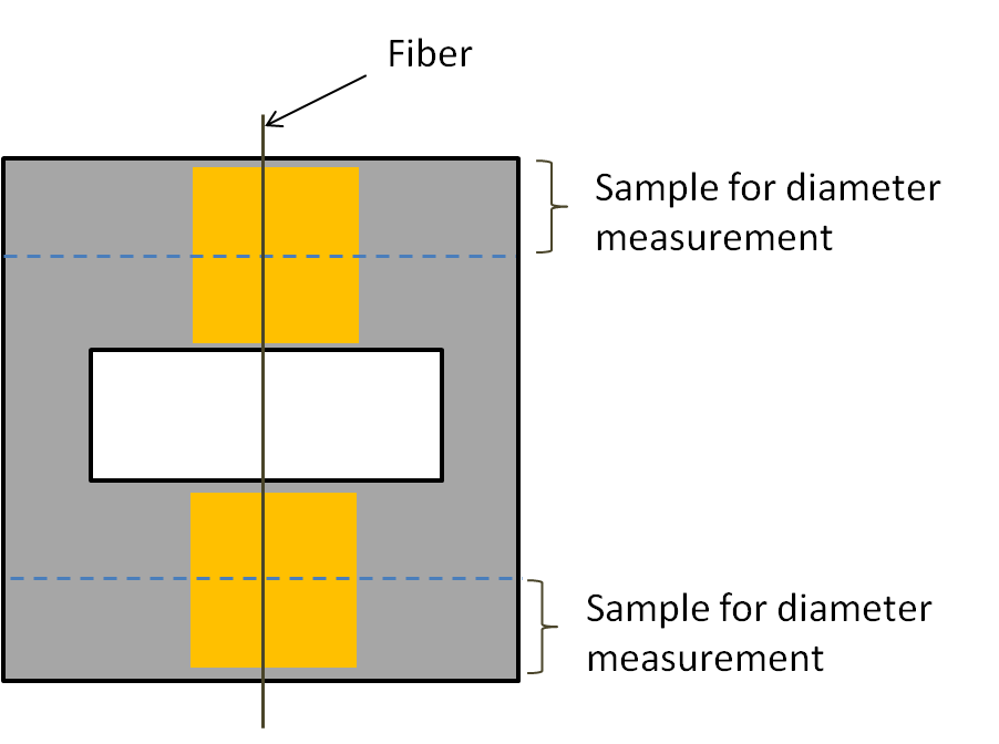
Cut off about 10 mm width off each edge of the frame where the double sided tapes and the fiber are for later measurement of fiber diameter (See figure 4). Label both the samples for diameter check and the sample for tensile testing.
|
| Figure 4. Illustration of segment of the frame to be cut off for measurement of fiber diameter |
Use a small piece of the frame material to cover the exposed double sided tape on the frame.
Store fiber sample in an enclosed box as any breeze may stretch the fiber.
3.2 Tensile testing
Mount the test specimen (test window frame with the fiber) on the tensile tester such that the grip is on the tabs holding the fiber.
Cut off a portion of the window frame as shown in the figure 5.
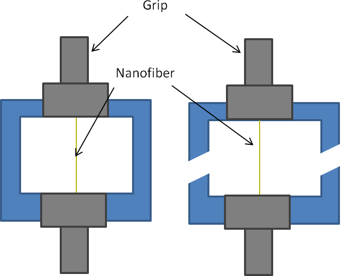
|
| Figure 5. Illustration of the the frame ribs to be cut off prior to application of tensile load |
Ensure the setting on the tensile tester is correct and start the test.
Recommended test parameters:
Gauge length: 10 mm
Strain rate: 1%/s
See Appendix A for summary of tensile test settings found in literature.
3.3 Acceptance criteria
Only fibers that failed at least 1 mm from the edge of the tab is being considered.
3.4 Diameter measurement
In electrospinning, the variance in the fiber diameter can be quite large. Therefore, it is important to get as close an estimate of the diameter of the tested fiber as possible. The frame for fiber collection is specially prepared with a broader edges so that a section at each ends of the fiber can be cut off from the frame to determine its diameter. This section will be labelled for identification with the section of the fiber used in tensile testing.
A SEM is required to capture an image of the fiber and its diameter may be determined using an image processing software such as ImageJ. The diameter of the fiber is the average value of the measurement taken off both segments of the fiber.
See Appendix B for alternative diameter determination methods.4. References
- Chen F, Peng X, Li T, Chen S, Wu XF, Reneker D H, Hou H (2008) Mechanical characterization of single high-strength electrospun polyimide nanofibres. J. Phys. D: Appl. Phys. 41, 025308.
- Chew S Y, Hufnagel T C, Lim C T, Leong K W. Mechanical properties of single electrospun drug-encapsulated nanofibres. Nanotechnology 2006; 17: 3880.
- Inai R, Kotaki M, Ramakrishna S (2005) Structure and properties of electrospun PLLA single nanofibres. Nanotechnology 16 pp. 208
- Tan EPS, Ng SY, Lim CT (2005) Tensile testing of a single ultrafine polymeric fiber. Biomaterials 26 pp. 1453
- Tan EPS, Lim CT (2006) Effects of annealing on the structural and mechanical properties of electrospun polymeric nanofibres. Nanotechnology 17 pp. 2649.
- Appendix A: Tensile Test Settings found in literature
- Appendix B: Diameter determination methods
- Appendix C: Breaking Load of single strand electrospun fiber
Last updated: 18 Dec 2013

