In some applications, it may not be necessary for the yarn to be made out of nanofiber strands only. In particular, for fabrics to take advantage of the high surface area of nanofibers, having nanofibers coating on the micro-filament may be sufficient. Researchers have come out with various set-ups to enable electrospun fibers to be coated on microfiber or filament.
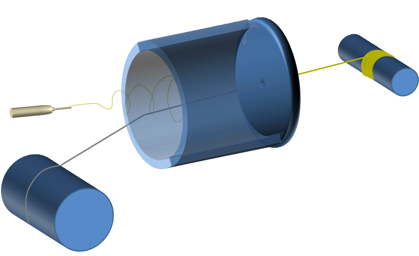
Thorvaldsson et al uses a Teflon cylinder to control the spread of the electrospinning jet such that the electrospun fibers will collide with the strand of microfiber within the cylinder (See figure 1)[Thorvaldsson et al 2008]. Using this setup, it was found that when the single strand microfiber is drawn through the cylinder at higher speed (21 x 10-3 m/s), the deposited nanofiber tends to be aligned [Thorvaldsson et al 2010] while at lower speed (5 x 10⁻³ m/s), the deposited nanofibers on the microfiber tends to have a more random arrangement. While the author did not provide any explanation for this observation, this phenomena may be due to preferential deposition of the nanofiber along the length of the microfiber resulting in the nanofiber alignment. Similar preferential alignment of electrospun fibers along the crest of protruded surfces have been observed [Neves et al 2007]. This is more obvious for higher speed drawing of the microfiber as the surface area exposed for the nanofibers to deposit is small. At lower speed, there is sufficient time for more electrospun fibers to be deposited on the fiber core and the larger resultant deposition area and electrical interference from the earlier deposited fibers resulted in random fiber deposition.
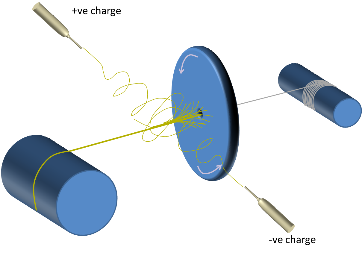
A slight modification of the setup involves using two opposing polarity electrospinning spinneret to deposit fibers on a rotating plate face as shown in figure 2. In this setup, a strand of microfiber or filament is drawn through the hole in the middle of the plate while the electrospinning jets are directed towards the hole. The rotation of the plate ensures that the electrospun fibers are twisted onto the moving microfiber through its center. The take-up speed for this technique is 1.8 x 10⁻³ m/s. Although this is much slower than the speed mentioned earlier, it still is able to form highly aligned nanofibers on the filament. This is probably due to the difference in the mechanism in which the electrospun fibers are being transferred onto the microfiber or filament. In the first method, electrospun fibers are deposited directly on the filament while in the second example, the electrospun fibers are collected off the plate and onto the filament.
In most electrospinning setups, a collector with neutral or opposing polarity is needed to initiate and draw the jet into nanofiber. Using alternating current (AC) high voltage for electrospinning, Valtera et al (2019) showed that the electrospinning jet self bundles into a plume of nanofiber in space without the need of a physical collector. With the plume of nanofibers, they were able to pass a polymer filament through it such that it is coated with the electrospun nanofibers. To produce sufficient volume of nanofibers, Valtera et al (2019) used a needleless spinning-electrode. The production rate of the polyvinylbutyral (PVB) envelope was 20 m/min, while the polyamide 6 (PA6) envelope was produced at the speed of 10 m/min. Madheswaran et al (2022) used the same concept of AC electrospinning to construct a nanofibrous sheath over a suture yarn made of either polyamide 6 or polyurethane. A needleless spinneret was used to electrospin a polymer solution containing antibacterial chlorhexidine (CHX). The core yarn passed across the path of the electrospinning jet and the nanofibers wrapped around the core yarn. The resultant composite yarn demonstrated antibacterial properties against Escherichia coli and Staphylococcus aureus. Tests using 3T3-SA mouse fibroblast cells showed that the composite yarn with CHX to be biocompatible.
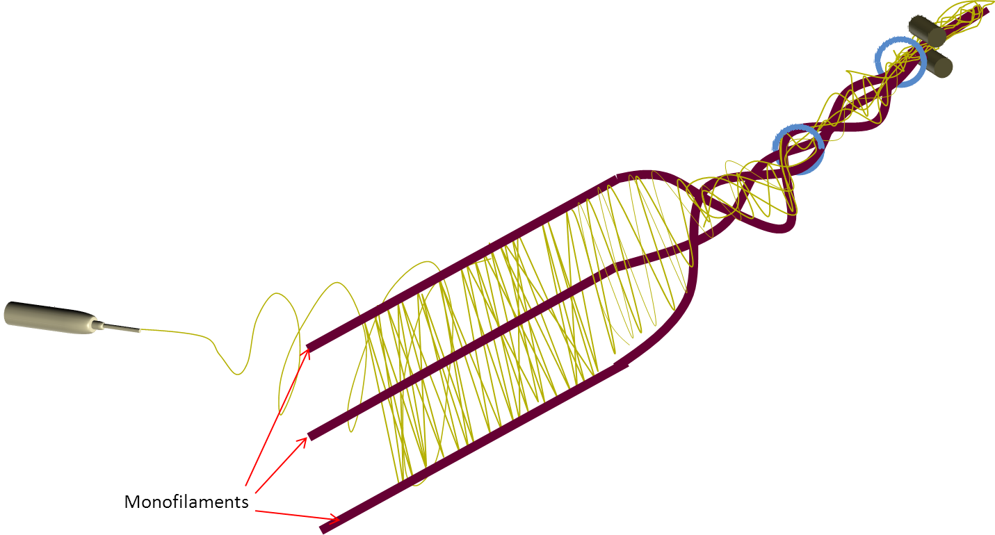
Since fiber yarn usually comes in the form of several monofilaments twisted together, electrospinning may be used to deposit nanofibers on several monofilaments followed by twisting to physically "tie-in" the nanofibers. This impact superior abrasion resistance to the nanocoating compared to microfibers with simply coated nanofibers.
A yarn with twisted or braided filaments is usually preferable over unidirectional aligned filaments as the former is able to transfer load across all the filaments. Generally, electrospinning is the rate determining step for manufacturing a hybrid nanofiber and microfiber yarn. To increase the speed of fabricating a twisted hybrid nanofiber and microfiber yarn, He et al (2014) separated the process of forming electrospun nanofiber yarn before coating and twisting a microfiber filament with the electrospun yarn. With a roll of electrospun polyacrylonitrile (PAN) nanofiber yarn and a PAN filament yarn, the two yarns were twisted together using an air-flow twisting chamber. The degree of twisting can be controlled by the air velocity and a production speed of up to 100 m/s can be achieved. Twisted nanofibers on the filament can be observed when the airflow pressure was below 0.5 MPa but above that, the nanofibers start to become disoriented as the fibers are being sheared off the monofilament surface. At optimum airflow pressure of 0.4 MPa, the hybrid PAN yarn showed greater yield strength (62.59 MPa) than pure filament yarn (18.25 MPa) and nanofiber yarn (32.34 MPa) [He et al 2014].
The technique and use of coated filament with electrospun fibers has been applied to the production of hollow nanofibrous yarns. Javazmi et al (2020) constructed compared single and double layered hollow nanofibrous yarns using electrospinning for the release of urea. The hollow nanofibrous yarns were constructed by electrospinning poly L-lactic acid (PLLA) nanofibre onto a polyvinyl alcohol (PVA) multifilament yarn. For double-layered hollow nanofibre yarns, polyhydroxybutyrate (PHB) nanofibres were electrospun on top of the poly L-lactic acid (PLLA) nanofibre layer. PVA multifilament yarn was subsequently removed by dipping the layered yarns in water to obtain the hollow nanofibre yarn. Urea in both single and double-layered hollow yarns were loaded into PLLA nanofibres. The urea loaded yarns were soaked in water and their nitrogen release rate was determined. In the first 12 h, the release rate of nitrogen for single and double-layered hollow yarns were 79% and 24% respectively. Single layer hollow yarns showed a burst release in the first 48 h but the release rate of double-layered yarn was more gradual. The much slower release rate of double-layered hollow yarns was due to the PHB nanofibres layer that acts as a physical barrier around the PLLA layer which delays the release of urea.
Published date: 19 Sep 2013
Last updated: 08 July 2022
▼ Reference
-
Javazmi L, Low T, Ash G, Young A. Investigation of slow release of urea from biodegradable single- and double-layered hollow nanofibre yarns. Sci Rep 2020; 10: 19619
Open Access
-
Neves N M, Campos R, Pedro A, Cunha J, Macedo F, Reis R L. Patterning of polymer nanofi ber meshes by electrospinning for biomedical applications. International Journal of Nanomedicine 2007; 2: 433
-
Ravandi, S A H, Sanatgar R H, Dabirian F. Wicking Phenomenon in Nanofiber-Coated Filament Yarns. Journal of Engineered Fibers and Fabrics 2013; 8: 10.
Open Access
-
He J X, Zhou Y M, Wu Y C, Liu R T. Nanofiber coated hybrid yarn fabricated by novel electrospinning-airflow twisting method. Surface and Coatings Technology 2014 ahead of press.
-
Madheswaran D, Sivan M, Valtera J, Kostakova E K, Egghe T, Asadian M, Novotny V, Nguyen N H A, Sevcu A, Morent R, Geyter N, Lukas D. Composite yarns with antibacterial nanofibrous sheaths produced by collectorless alternating-current electrospinning for suture applications. J Appl Polym Sci 2022; 139: 51851.
-
Thorvaldsson A, Stenhamre H, Gatenholm P and Walkenstrom P (2008) Electrospinning of Highly Porous Scaffolds for Cartilage Regeneration. Biomacromolecules 9 1044-1049
-
Thorvaldsson A, Engstrom J, Gatenholm P, Walkenstrom P. Controlling the Architecture of Nanofiber-Coated Microfibers Using Electrospinning. J Appl Polym Sci 2010; 118: 511-517
-
Valtera J, Kalous T, Pokorny P, Batka O, Bilek M, Chvojka J, Mikes P, Kostakova E K, Zabka P, Ornstova J, Beran J, Stanishevsky A, Lukas D. Fabrication of dual-functional composite yarns with a nanofibrous envelope using high throughput AC needleless and collectorless electrospinning. Scientific Reports 2019; 9: 1801.
Open Access
-
Zhou F L, Gong R H, Porat I. Nano-coated hybrid yarns using electrospinning. Surface & Coatings Technology 2010; 204: 3459.
▲ Close list
 ElectrospinTech


