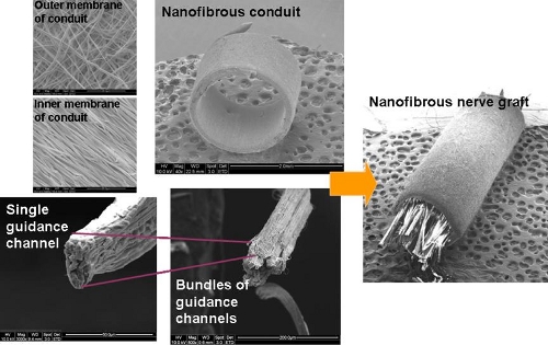
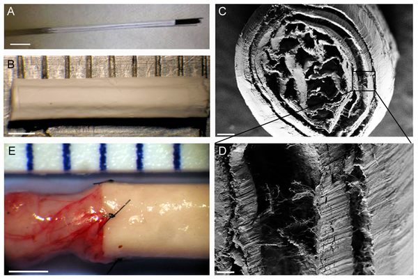
To mimick peripheral nerve, a nanofibrous assembly consisting of a nanofibrous tube and nanofibrous yarn in the lumen of the tube was constructed by Koh et al (2010). The tubular scaffold was fabricated by depositing nanofibers on a rotating rod followed by the removal of the tube from the rod. Nanofibrous yarn was constructed using a liquid flow method although other methods that can produced aligned fibers yarn can be used. A bundle of yarns were gathered and thread through the lumen of the tube and this can be done using a metal hook.
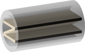
Clements et al (2009) used the contact guidance ability of nanofibers to construct a hybrid setup comprising of aligned nanofiber membrane and commercially available nerve tube [Clements et al 2009]. The tube was first cut into segments to allow placement of the membrane inside before gluing back together. The membrane with nanofibers aligned in the longitudinal axis of the tube was glued into the tube. Two different configurations were constructed as shown in the diagrams below.
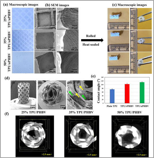
A simple way of introducing luminal structure is to roll a relatively stiff membrane into a conduit with a spiral cross section. Zennifer et al (2025) used a combination of 3D-printed thermoplastic polyurethane (TPU) fiber lattice and electrospun poly(3-hydroxybutyrate-co-3-hydroxyvalerate) (PHBV) (PHBV) fibers to first form a flat sheet. The sheet is subsequently rolled tightly using a steel rod and heat sealed to form a conduit. An advantage of using 3D printing is that the infill density of the grid structure can be controlled. The electrospun fibers were deposited directly on the 3D printed grid. Aligned fibers were obtained by electrospinning on the printed grid mounted on a rotating drum. To enhance contact guidance of the peripheral nerve, the electrospun aligned fibers were oriented along the length of the conduit. In vivo tests using 10 mm sciatic nerve defect in Wistar rats treated with the conduit showed muscle innervation and axon healing comparable to autografts over 4 months.
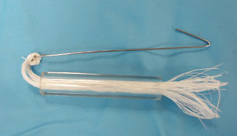
For the nerve guidance conduit described by Koh et al 2010, it is also possible to use the nanofibrous yarn with commercially available tube since both components (yarn and tube) are manufactured separately before combining. As seen in the picture below, a simple hook design can be used to push the bundle of yarns into a tube. The density of the yarn can be varied to achieve a balance between contact guidance and obstruction of nerve axon.
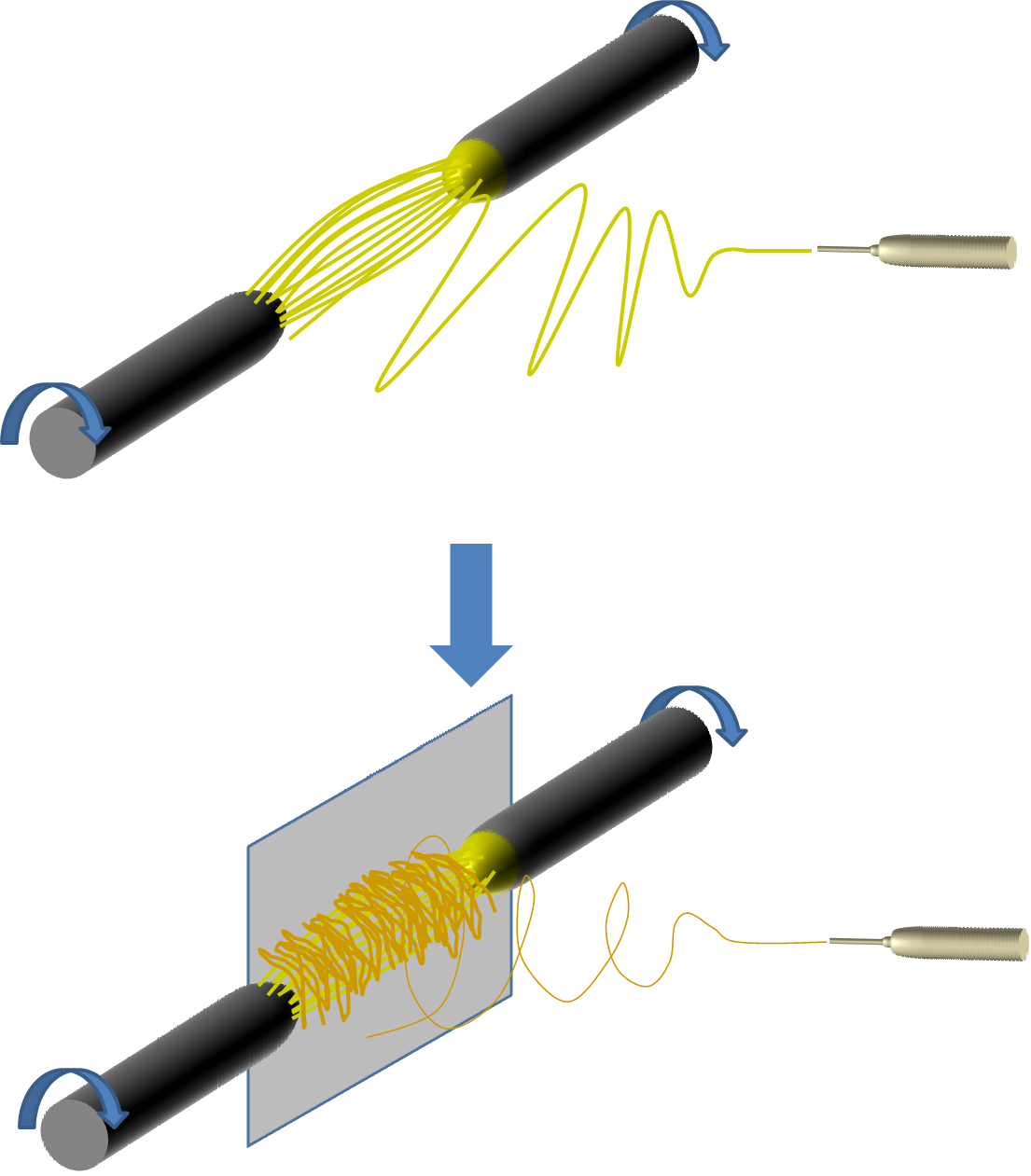
A common drawback of guidance channel or film is that the materials used for guiding are themselves a barrier to axon growth or neurite. In a scaffold developed by Brown (2012) to be used for spinal cord treatment, its architecture introduces guidance function while minimizes neurite obstruction. Instead of fibrous yarn or film which creates a large signature, longitudinally aligned electrospun monofilaments were assembled in the lumen and encapsulated with an outer nanofibrous covering. A clear advantage of monofilaments is that the individual cross sectional diameter is so small that neurite may easily get pass it. The challenge is to create spacings between the filaments that is sufficiently large for the neurite to get through. The study has already demonstrated alignment of endothelial cells at its core and it is likely that neurite will be guided through as well.
Construction of this scaffold is based on two electrospinning setup concepts. To form the longitudinally aligned monofilament core, a parallel electrodes setup was used. The electrodes may be made out of small diameter rods with their ends facing one another. This way, fibers will bridge across the gap while charges on each fiber will cause them to repel one another, thereby creating the space for neurite growth. Next, without removing the fibers from the rods, the fibers (while still attached to the rod) are placed against a flat plate. A schematic of the process is shown in the figure below. Electrospinning is then carried out to depost more fibers over the longitudinally aligned fibers. Due to the presence of the repulsive longitudinally aligned fibers, the subsequent electrospinning jet tends to deposit the fibers across the longitudinally aligned fibers. The deposited fibers are used to wrap the longitudinally aligned fibers.
A closer mimicry of the peripheral nerve extracellular matrix (ECM) is to reconstruct the endoneural tubes within a sheath. Dinis et al (2014) used a parallel electrodes collector system to collect highly aligned nanofiber membrane. A small diameter Teflon stick (0.3 mm diameter) is used to roll the membrane with the fiber alignment along the long axis of the rod to reconstruct the endoneural tubes. Several of these "channels" are then rolled into a larger sheath which is also comprised of fibers aligned along the length of the tube. While
in vitro studies of cell alignment on aligned fibrous membrane is promising, it remains to be seen whether such a structure would do well
in vivo.
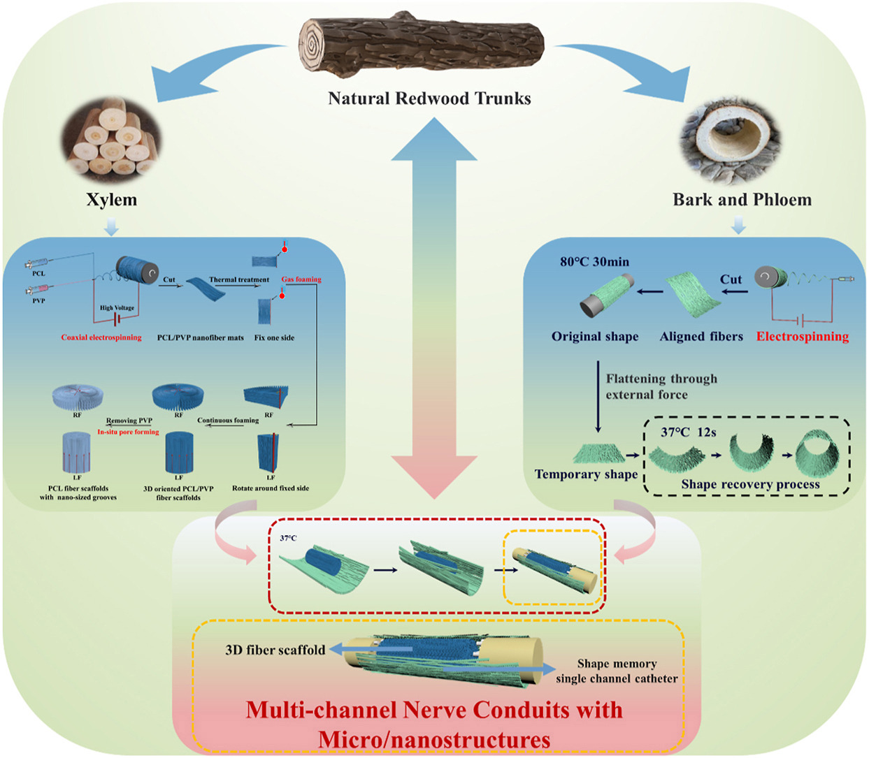
Wang et al (2024) constructed an electrospun assembly using an electrospun tube with longitudinally aligned fibers and grooves and an interior filled with expanded electrospun scaffold with longitudinal alignment. Core-shell polyvinylpyrrolidone (PVP)/poly l-lactic acid-co-trimethylene carbonate (PLATMC) was prepared using electrospinning with different ratios of PVP and shape memory PLATMC to form the conduit. PLATMC is a shape memory material hence the electrospun membrane can be fixed in a tubular shape, opened up and recovered after electrospun fillers were placed inside. The fillers were made of electrospun aligned nanofibrous PCL/PVP membrane expanded into a 3D form using a gas foaming method. An in vivo rat model with a 10 mm sciatic nerve defect demonstrated good peripheral nerve regeneration and motor function comparable to autografts and much better than the group with just an empty conduit.
Published date: 05 Nov 2012
Last updated: 11 November 2025
▼ Reference
-
Brown D E. Angiogenesis in Response to Varying Fiber Size in an Electrospun Scaffold In Vivo. MSc Thesis. Virginia Commonwealth University 2012.
Open Access
-
Clements I P, Kim Y T, English A W, Lu X, Chung A, Bellamkonda R V (2009) Thin-film enhanced nerve guidance channels for peripheral nerve repair. Biomaterials 30 pp. 3834.
-
Dinis TM, Vidal G, Jose RR, Vigneron P, Bresson D, et al. (2014) Complementary Effects of Two Growth Factors in Multifunctionalized Silk Nanofibers for Nerve Reconstruction. PLoS ONE 9(10): e109770. doi:10.1371/journal.pone.0109770
Open Access
-
Koh H S, Yong T, Teo W E, Chan C K, Puhaidran M E, Tan T C, Lim A, Lim B H. Ramakrishna S. (2010) In vivo study on novel nanofibrous intra-luminal guidance channels to promote nerve regeneration. Journal of Neural Engineering vol. 7 pg. 046003 (14pp).
-
Wang X, Chen S, Chen X, Wu J, Huang Z, Wang J, Chen F, Liu C. Biomimetic multi-channel nerve conduits with micro/nanostructures for rapid nerve repair. Bioactive Materials 2024; 41: 577.
https://www.sciencedirect.com/science/article/pii/S2452199X24002895 Open Access
-
Zennifer A, Kumar S K P, Bagewadi S, Unnamalai S, Chellappan D, Abdulmalik S, Yu X, Sethuraman S, Sundaramurthi D, Kumbar S G. Innovative spiral nerve conduits: Addressing nutrient transport and cellular activity for critical-sized nerve defects. Bioactive Materials 2025; 44; 544.
https://www.sciencedirect.com/science/article/pii/S2452199X2400481X Open Access.
▲ Close list
 ElectrospinTech