The collector has a significant effect on the productivity and arrangement of the nanofibers and the final structure. This is due to its infuence on the ability of the charges on deposited fibers to be conducted to ground which in turn affects the amount of fibers that are collected on the substrate. For a less conductive collector, deposited fibers may retain some of its charges and this will repel incoming fiber thereby reducing fiber deposition and productivity [Stanger J et al 2009]. Even slight variation in the electric field profile on the collector surface has been shown to influence fiber deposition [Chanunpanich et al 2008]. Despite differences in the influence of charge retention due to collector material, its effect on electrospun fiber diameter seems to be minimal [Adomaviciute et al 2011). Adomaviciute et al (2011) studied the effect of different support materials (polypropylene, polyethylene, polyethylene terephthalate, aluminum, acetate fiber, paper) and grounding electrodes (drum, wire or support material 40 mm from wire electrode) located behind the supporting material on the collection of polyvinyl alcohol (PVA) using free surface electrospinning (Nanospider from Elmarco). It was found that the type of grounding electrodes have a greater influence on the number of fibers collected than the support material with the drum electrode having the most fiber collected. This is probably due to greater potential difference generated between the solution surface and the wider surface area of drum grounding electrode.
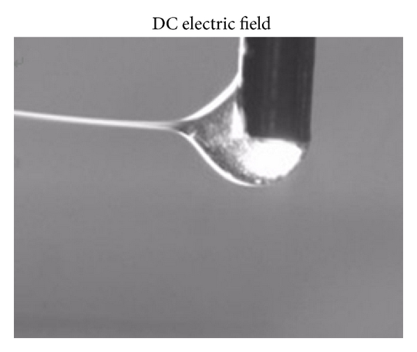
Charge retention on an insulating collector material eg. polyethylene terephthalate, has been shown to affect construction of ordered structures in near field electrospinning [Zheng et al 2014]. The retained charges has been shown to be sufficiently large to deflect the electrospinning jet from its nozzle tip when a typical DC high voltage power supply was used to charge the solution.
Electrospinning process involves the evaporation of solvents from the electrospinning jet to form solid fibers at the collector. To facilitate formation and collection of dry fibers, the collector may be heated. A heated collector may also increase the ambient temperature around the electrospinning jet which increases evaporation of the solvent and reduces the viscosity of the electrospinning solution. Morsy (2022) showed that at a higher collector temperature, the diameter of the collected electrospun gelatin fiber is reduced. When the collector surface temperature was below 50 °C, the average diameter of the gelatin fibers was about 680 nm. At 50 °C, the fiber diameters were reduced to 420 nm. Further increase in temperature to 75 °C and 100 °C gave a stable fiber diameter of around 380 nm. The gelatin for electrospinning was dissolved in acetic acid which has a boiling point of 118 °C. At temperature between 50 to 100 °C, there may be a significant reduction in the viscosity of the gelatin solution without a significant increase in the evaporation of the solvent near the tip of the nozzle. Therefore, significant thinning of the fibers were observed without disruption to the electrospinning process.
To encourage fiber deposition on collector with material of low conductivity, reduction in the charge density of the electrospinning jet may be facilitated through the reduction of residual charge build-up. Kim et al (2009) was able to deposit electrospun polycaprolactone on latex through the use of blower, focusing electrode and steering electrodes. In particular, through application of AC high voltage on the steering electrode, they were able to reduce the amount of charges on the depositing fibers and encouraging fiber deposition on a non-conductive surface. Kessick et al (2004) was also able to deposit fibers on non-conducting surface using AC high voltage electrospinning where an AC high voltage instead of a typical DC high voltage was applied to the nozzle. Similarly Zheng et al (2014) was able to construct ordered fiber using an AC high voltage power supply for depositing fibers on a non-conducting polyethylene terephthalate collector. For hydrophilic base-materials such as cellulose, increasing its conductivity for attracting electrospun fibers may be as simple as wetting the deposition surface by spraying prior to electrospinning [Hakala and Heikkila 2011].
Left. Deflected electrospinning jet in near field electrospinning due to charge retention of deposited fibers on insulating substrate when DC high voltage power supply was used.
Right. Vertical electrospinning jet in the same setup when an AC high voltage was used due to reduced charge on deposited fibers.
[Zheng et al 2014. Journal of Nanomaterials, vol. 2014, Article ID 708186, 7 pages, 2014. doi:10.1155/2014/708186. This work is licensed under a Creative Commons Attribution 3.0 Unported License.]
Less commonly investigated is the benefit of deliberate positioning of the collector relative to the electrospinning source. In most electrospinning setup, the nozzle is located at the top and the collector at the bottom. It is only in free surface electrospinning and its variants that the positions get switched around. A less spoken advantage of having the free surface electrospinning source at the bottom is that the polymer solution was made to travel against the gravitational pull. This may help to reduce the formation of beads and droplets due to excess solution feeding [Prabu et al 2020]. The advantage of having an electrospinning source at the bottom and collector on top may also be found in nozzle tip electrospinning. In electrospinning of some solutions, accumulation of partially solidified solutions at the nozzle tip may occur. In a nozzle top, collector bottom arrangement, dislodging the partially solidified material at the nozzle may cause it to drop on the collected membrane below, hence affecting its quality. However, when the position gets switched around, with the nozzle at the bottom instead, dislodged semi-solid material at the nozzle may fall on the ground under its weight and away from the electrospun membrane above. Using the same logic, the nozzle to collector placement may be horizontal instead of vertical. Similarly, dislodged material will fall onto the ground in the space between the nozzle and the collector instead of at the collector.
Interestingly, Al-Hazeem et al (2021) reported that the nozzle position relative to the collector has a significant impact on the characteristics of electrospun polyvinylpyrrolidone (PVP)/TiO2 fibers. While they have performed experiments on electrospinning with the nozzle and collector from vertically top-down, diagonal, horizontally and bottom-up, of more significance was vertically top-down and bottom-up positions. In a vertically top-down (nozzle on top, collector below) setting, the electrospinning jet and the force of gravity acts in the same direction. Conversely, in a bottom-up setting, the gravity force is pulling down while the electrospinning jet is moving upwards in the opposing direction. While gravitational force on the electrospinning jet is a weak force, it's effect can be seen in the crystallinity of the electrospun fibers. XRD examination showed eight 2θ distinct peaks on the electrospun fibers due to TiO2 from the bottom-top setting while only five peaks were found on the top-down setup with four peaks barely visible. This shows greater crystallinity of electrospun fibers from the bottom-up setting. The fibers produced from the bottom-up setting also showed the smallest average diameter of 75 nm.
This simple adjustment in nozzle to collector position will help to achieve better quality membrane.
Most electrospinning collectors comprises of a flat and smooth surface. However, collector with surface topography may give a more desirable outcome in particular with mass production. A featureless surface gives a uniform electric field profile and the electrospinning jets will self organize and deposit fibers on points on the collector with the greatest potential difference. This often led to non-uniform fiber distribution. When the collector features numerous sharp points and given a high voltage, it encourages the electrospinning jet to travel to discrete points on the collector. When the discrete points are optimally spaced, the jets will attempt to cover all the points on the collector resulting in a more uniform fiber coverage. This setup has been shown to produce uniform fiber distribution in a mass production melt electrospinning setup [Koenig et al 2019].
Understanding the influence of electric field between the nozzle and collector, nature of the collector and adhesion of the electrospun fibers to the collector will explain the characteristics of resultant fibers and membrane. Wei et al (2025) compared the electrospun fibers membrane collected on an aluminium (Al) surface and top and bottom surface of pig skin. With Al surface, the deposit polylactic acid (PLLA)/gelatin (GL) fibers were mostly straight while on the pig skin surfaces, the fibers were curved. This can be understood by the stronger electric field acting on the conductive Al surface and the adhesion of the fibers to the surface which favours the collection of straight fibers. Pig skin is insulating and probably is less adhesive for the electrospun fibers and this generally favours more curved fibers. The membrane deposited on the pig skin also showed greater surface roughness and air permeability. Wound healing tests on rats showed that electrospun membrane formed on pig skin stop had the best recovery. Wei et al (2025) attributed this to the pore-mimic structure of the electrospun membrane with scattered small pores of 50 µm. The scattered small pores were in turn attributed to the presence of hairs on top of the outer pig skin surfaces.
Deliberate movements of the collector may be used to generate a more uniform fiber distribution. In a static collector, the electrospinning jet travels along the path of the highest potential gradient, which is (potential difference)/(path distance). As fiber gets deposited, insulation and residual charges build up shifts the path to the next highest potential gradient. This often results in the highest fiber density directly below the nozzle and spreading thinner towards the edge of the collector. A rotating collector moving laterally will help to spread the electrospinning jet along the length of the collector but this may result in preferential fiber orientation causing asymmetrical properties. More complex collector movement has been used to improve electrospun fibers mat uniformity. Pathalamuthu et al (2019) describes a spirograph-based collector movement for collection of electrospun polyacrylonitrile (PAN) fibres. The spiropath path comprises of multiple circular movement passing through a point centre. Movement speed of the collector need to be kept below 300 rpm or the air flow generated by the collector movement would disrupt the depositing jet. On a static collector, the coefficient of variation was 12.5%. However, the coefficient of variation with the spirograph-based collector movement was 2.4%. This demonstrated a significant improvement in electrospun mat thickness uniformity.
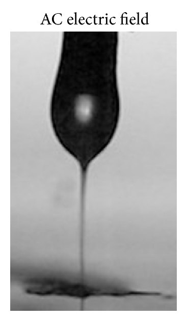
In most conventional electrospinning setup, the orientation of the nozzle and the collector is along a single axis. It is common to see electrospun fibers deposited beyond the edge of the collector surface leading to wastage. An alternative form is to surround the electrospinning jets with a cylindrical collector. Gilmore et al (2024) constructed an electrospinning spinneret that featured a hollow disk extruder with evenly spaced radial holes. A cylindrical collector surrounds the spinneret so that most of the fibers can be collected within the cylinder. To facilitate even distribution of fibers, the cylindrical collector rotates slowly around the spinneret. With 24 extruder holes, this setup was able to produce fibers at a rate of 2.6 g/h which was 15 times faster than the conventional single needle flat plate setup. However, while the conventional single needle flat plate setup produced fibers with diameter of 643 nm, the same solution using the cylindrical collector produced fibers with diameter of 2595 nm. Such a significant difference in fiber diameter despite having the same tip to collector distance may be due to greater accumulation of charges in the cylindrical collector leading to a weaker potential difference. This reduces the degree of fiber stretching and results in thicker fibers.
High throughput electrospinning prototype and improved system used in this study. (a) HTES prototype extruder and collector electrospinning discrete mats of fibers. (b) Hollow disk extruder top (left) and bottom (right) with capillary holes. The 12 larger holes on top are for screws to attach the two halves. (c) Improved HTES setup used in this study with collector, fluid pump, and power supply labelled. (d) Inside the collector with extruder disk and collector labelled. [Gilmore et al 2025].
In some cases, the collector needs to be in the form of a coagulation bath so that fibers can be formed. This is often required for electrospinning solution that is unable to sufficiently dry during the flight from the spinneret to the collector. This is especially so for some water soluble polymers where the fibers are not sufficiently dry when they reach the collector. A coagulant such as ethanol may be used to quickly remove the water from the fibers such that they do not fuse together. Kong and Ziegler (2014) used an ethanol coagulant for the collection of electrospun pullulan fibers. Sutjarittangtham et al (2014) used an ethanol bath cooled to -20°C for the collection of electropun natural tapioca starch (NTS) aqueous solution. This is necessary to quickly dehydrate the wet NTS fibers. The NTS fibers have a diameter distribution of 1.3 to 14.5 µm.
A coagulation bath collector may also be used for other purpose even if the electrospinning does not require it. Zhu et al (2012) used a coagulation bath to quickly solidify the electrospinning jet at varying collection distance to observe the evolution of the fiber formation as the jet accelerates from the spinneret. Zheng et al (2014) prepared an aqueous suspension of magnesium hydroxide nanoparticles for collecting electrospun cellulose fibers. As the cellulose fibers are formed in the aqueous suspension, the magnesium hydroxide nanoparticles adhered on the surface of the fibers giving them a fire resistant property.
Taking the concept of a coagulation bath for collecting fibers further, a wetted surface may be designated as a collector. In this case, a hydrophilic material with wetted surface is more favorable for electrospun fiber deposition compared to an insulating hydrophobic surface. Choi et al (2017) demonstrated the selectivity of electrospinning jet deposition with a patterned collector surface comprising of plasma treated hydrophilic acrylic regions and the other non-treated hydrophobic regions. A high humidity was maintained at the collector site such that a thin layer of water molecules are formed on the hydrophilic surface. Their results demonstrated that hydrophilic surface was able to perform like a conductive electrode collector. When there is a parallel strip of hydrophilic regions with insulating hydrophobic region in between, the fibers would align across the hydrophobic region similar to conventional parallel electrode collector setup.
The electrospinning process generally coats a layer of nanofibers on any collector which may comes in the form of flat plate, tubes or even a coagulation bath. Collection of nanofibers in the form of a nonwoven mesh on a smooth plate is the most commonly encountered. Using flat plate collector of different topographies such as grid mesh [Gibson et al 2004; Neves et al 2007] and plate with array of protrusions [Ding et al 2009] can produce patterned membrane consisting of regions of different fiber density. The patterned membrane has been shown to have better tear resistance than non-patterned membrane [Gibson et al 2004]. Patterned membrane has also been tested for its influence on cell behavior [Neves et al 2007] although the benefit may not be very obvious. Nanofibers can also be coated on a rod and the rod can later be withdrawn to form nanofibrous tubes. The same method has also been used to coat nanofiber on stent to reduce in-stent restenosis and to coat on microfiber mat.
There are generally two methods (and their hybrid) for collecting aligned fibers. A simple method is by using rotating drum collector at high speed. This has the advantage of gathering aligned fibers over a large area. Fiber diameter is also influenced by the rotation speed of the collector with higher rotation resulting in smaller diameter fibers [Becker et al 2015]. This is due to the mechanical drawing of the fiber as it is deposited on the collector. Even at low drum collector rotation speed where the electrospun fibers are randomly distributed, the fiber diameter is lower than that of a static plate collector. The standard deviation of the fiber diameter is also smaller for rotating drum collector [Cavdar et al 2019]. As the fibers are drawn by the moving collector, the larger diameter fibers are drawn to a greater extent than smaller diameter fibers hence the reduction in standard deviation and overall fiber diameter. It will be interesting to verify this effect for higher collector rotation rate. However, excessive drawing has been shown to result in necking and fiber breakage [Zussman et al 2003]. The ductility of the material used may need to be considered when using rotating collector to construct aligned membrane due to the drawing force of the process. In general, the quality of fiber alignment is usually not as good as the method which uses electric field to control fiber alignment. By having an air gap between two or more collection electrodes, the fibers can be encouraged to oriented across the gap and give rise to more ordered structures. However, its disadvantage is the limitation of the area and thickness of the membrane which can be collected.
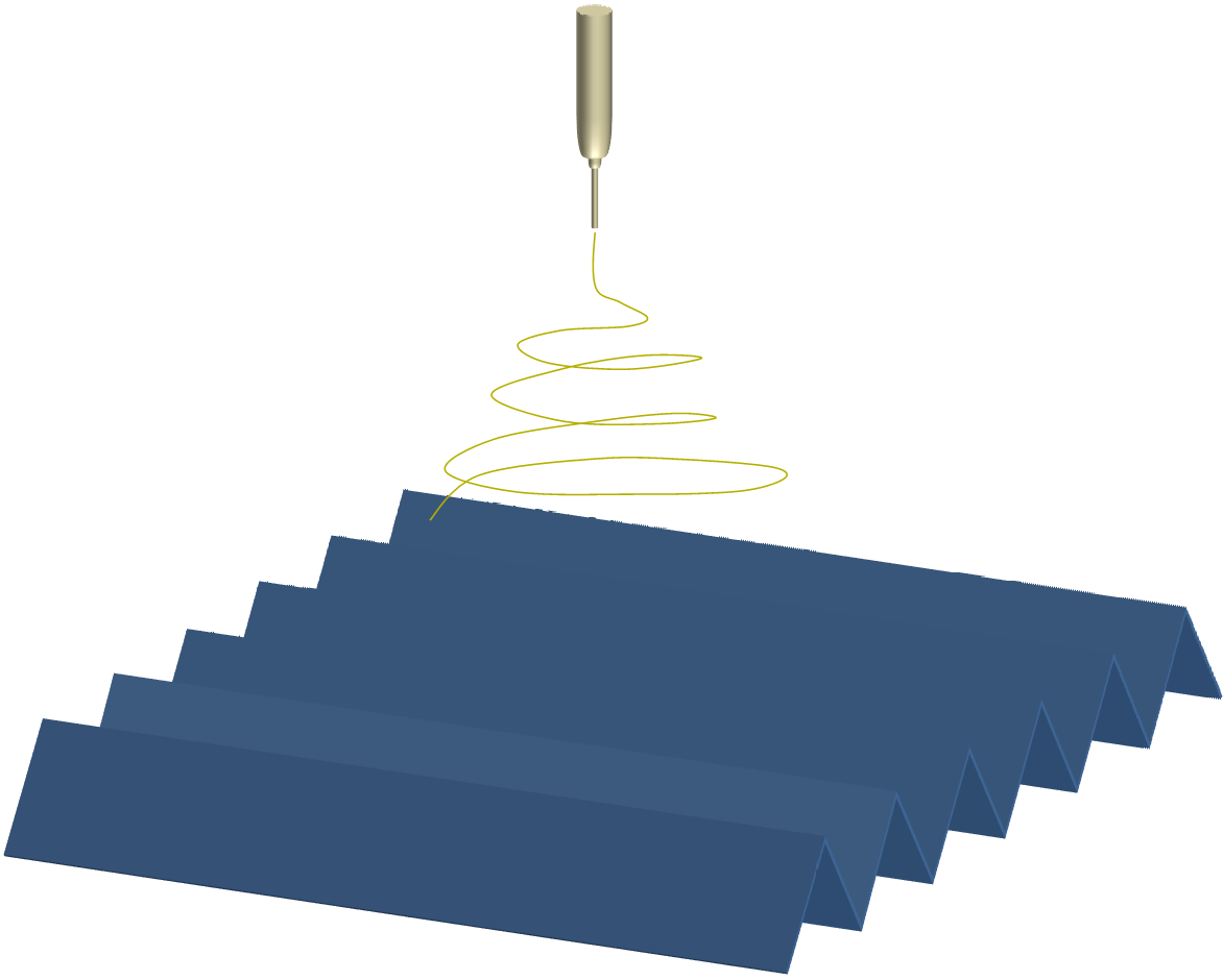
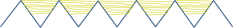
In an innovative improvisation of the parallel collection electrode setup, Liu et al (2011) used a series of ridges arranged in parallel to collect dry fibers which will otherwise be wet and fused if a flat plate collector is used. The solution electrospun by Liu et al (2011) was hyaluronic acid in a solvent mixture of deionized water, formic acid and N,N-dimethyl formamide. The low volatility of the solvent mixture causes the fiber to fuse and formed film instead of fibers when collected on a flat plate. Using a collector consisting of multiple ridges, the fibers are encouraged to deposit across the ridges. Due to the presence of residual charges, incoming fibers will be deposited higher up the ridge and this prevent contact between the fibers.
Top. Schematic of electrospinning over a collector made of ridges arranged in parallel.
Bottom. Illustration of the fiber deposited across the ridges which minimizes contact between fibers.
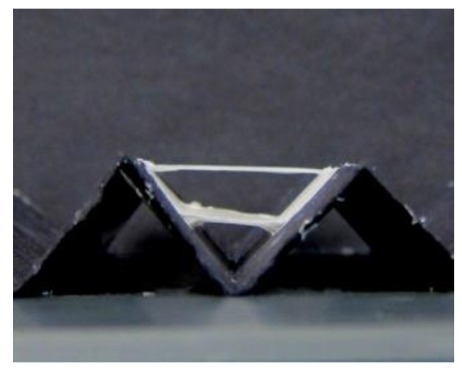
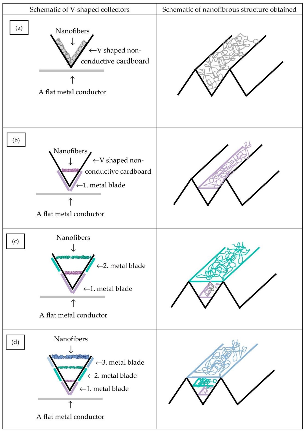
In an interesting example of how the material of the collector affects the fiber deposition behavior, the same ridges or corrugated profile collector used by Liu et al (2011) give rise to a fibrous structure that is different from Lubasova et al (2020). Although the general profile of the collector is the same, the material used is different. Liu et al (2011) collector is metal while Lubasova et al (2020) is a non-conductive cardboard substrate and metal plates were placed behind the cardboard substrate to direct fiber deposition. When the whole collector is conductive and electrically grounded, the fibers are spaced into the depth of the ridge and across the space. With a non-conductive cardboard substrate and metal plates behind, the fibers are deposited along the walls of the ridge and where it straddles across the space between the ridge wall, they are concentrated at the plane where the edge of the plate is. This showed that the electrospinning jet can be very sensitive to small differences in the electric field. While the preference for electrospinning to deposit fibers across the V ridge is useful for collecting aligned fibers, the same behavior is unhelpful for coating concave parts of an undulating surface.
The electrospinning jet typically travels along the line where the potential difference is the greatest. The greater the potential difference between the point on the collector and the nozzle tip, the more likely that the fiber would deposit on that point. Conversely, when the potential difference is less, the spread of the fibers on the collector will be greater. For more uniform deposition of fibers on an uneven surface, a less conductive collector may be better. Bauer et al (2022) showed that electrospun fibers were able to deposit on the concave surface of a funnel made of conductive polylactic acid (PLA) material. Similarly, a lower applied voltage was also found to allow fiber deposition in lower areas [Buer et al 2022].
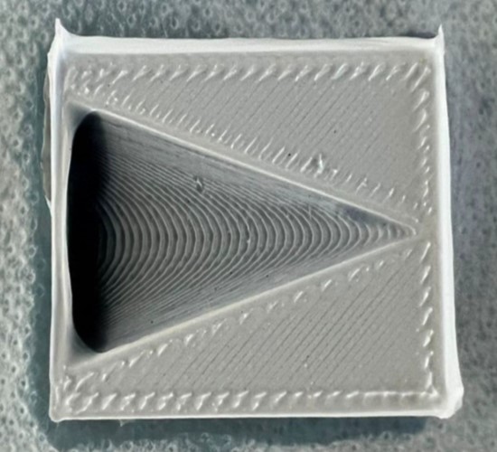
PAN electrospun on a funnel with a length of 40 mm and width of 31 mm, printed with Conductive PLA [Bauer et al 2022].
Photographic image showing two nanofiber bridges between the two sides of the V-shaped substrate [Lubasova et al 2020].
Schematic of 3-D nanofibrous layer producing setups for variations A-D (a-d) [Lubasova et al 2020].
The relative ease of coating nanofiber on almost any surface has led to various innovative methods to construct structures beyond two dimensional nanofiber mesh and to form yarns and three-dimensional block structures. Notable advancement has been in the collection of nanofibers on a coagulation bath. The fluid nature of a coagulation bath allows the deposited nanofibers to be assembled to form yarns and three-dimensional blocks.
Tube collector by pippuzzus
Point to point collector by Sherkarjha
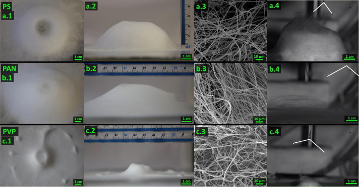
Deliberate placement of guiding electrodes on the collector has also been shown to encourage the formation of 3D standing structures. Vong et al (2021) showed that with a ring guiding electrode, they were able to get a relatively fast buildup of electrospun fibers. With a ring guiding electrode on the collector, the electrospinning jet will be depositing fibers along the edges of the ring. This will lead to a faster accumulation of fibers on the edges and the inner ring which facilitates fiber buildup. With this setup and an optimal distance between nozzle tip and collector of 5 cm, Vong et al (2021) was able to get polystyrene (PS) and polyacrylonitrile (PAN) fibrous scaffolds of 3 cm thickness after 10 min of deposition with the electrospinning nozzle circling over the ring. However with polyvinylpyrrolidone (PVP), the build profile is less ideal with a 1 cm buildup of fibers at the center of the ring.
3D electrospun structures of PS, PAN and PVP. (a.1) Top-view, (a.2) Side view, (a.3) SEM pictures and (a.4) High FPS camera picture during electrospinning of 3D PS. (b.1), (b.2), (b.3) and (b.4) are for 3D PAN. (c.1), (c.2), (c.3) and (c.0.4) are for 3D PVP [Vong et al 2021].
Published date: 10 June 2012
Last updated: 02 June 2026
Adomaviciute E, Stanys S. Formation of Electrospun PVA Mats on Different Types of Support Materials Using Various Kinds of Grounded Electrodes. Fibers & Textiles in Eastern Europe 2011; 19: 34.
Open Access
Al-Hazeem N Z, Ahmed N M, Jafri M Z M, Ramizy A. The effect of deposition angle on morphology and diameter of electrospun TiO2/PVP nanofibers. Nanocomposites 2021; 7: 70.
Open Access
Bauer L, Brandstäter L, Letmate M, Palachandran M, Wadehn FO, Wolfschmidt C, Grothe T, Güth U, Ehrmann A. Electrospinning for the Modification of 3D Objects for the Potential Use in Tissue Engineering. Technologies. 2022; 10(3):66. https://www.mdpi.com/2227-7080/10/3/66/htm
Open Access
Becker A, Zernetsch H, Mueller M, Glasmacher B. A novel coaxial nozzle for in-process adjustment of electrospun scaffolds' fiber diameter. Current Directions in Biomedical Engineering 2015; 1: 104.
Open Access
Cavdar F Y, UGUZ A. A comparative study of electrospinning process for two different collectors: The effect of the collecting method on the nanofiber diameters. Mechanical Engineering Journal 2019 Article in press.
Open Access
Chanunpanich N, Lee B, Byun H. A Study of Electrospun PVDF on PET Sheet. Macromolecular Research 2008; 16: 212.
Choi W, Kim G H, Shin J H, Lim G, An T. Electrospinning onto Insulating Substrates by Controlling Surface Wettability and Humidity. Nanoscale Research Letters 2017; 12:610.
Open Access
Ding Z, Salim A, Ziaie B (2009) Selective Nanofiber Deposition through Field-Enhanced Electrospinning. Langmuir 25(17), 9648-9652
Gibson P, Schreuder-Gibson H (2004) Patterned Electrospray Fiber Structures. INJ Summer pp. 34.
Open Access
Hakala T, Heikkila P. Press Felts Coated with Electrospun Nanofibres. Fibers & Textiles in Eastern Europe 2011; 19: 89.
Open Access
Kessick R, Fenn J, Tepper G. The use of AC potentials in electrospraying and electrospinning processes. Polymer 2004; 45: 2981.
Kim G H, Yoon H, Lee H N, Park G M. Polycarprolactone Ultrafine Fiber Membrane Fabricated Using a Charge-reduced Electrohydrodynamic Process. Macromolecular Research 2009; 17: 533.
Koenig K, Beukenberg K, Langensiepen F, Seide G. A new prototype melt-electrospinning device for the production of biobased thermoplastic sub-microfibers and nanofibers. Biomaterials Research 2019; 23: 10.
Open Access
Kong L, Ziegler G R. Rheological aspects in fabricating pullulan fibers by electro-wetspinning. Food Hydrocolloids 2014; 38: 220.
Liu Y, Ma G, Fang D, Xu J, Zhang H, Nie J. Effects of solution properties and electric field on the electrospinning of hyaluronic acid. Carbohydrate Polymers 2011; 83: 1011.
Lubasova D, Netravali A N. A Novel Method for Electrospinning Nanofibrous 3-D Structures. Fibers 2020; 8(5): 27.
Open Access
Morsy R. Influence of substrate temperature parameter on electrospinning process: example of application to the formation of gelatin fibers. Polym. Bull. (2022).
Open Access
Neves N M, Campos R, Pedro A, Cunha J, Macedo F, Reis R (2007) Patterning of polymer nanofiber meshes by electrospinning for biomedical applications. Int J Nanomedicine 2 pp. 433.
Open Access
Pathalamuthu P, Siddharthan A, Giridev V R. Spirograph based electrospinning system for producing fibre mat with near uniform mechanical property. Indian Journal of Fibre & Textile Research (IJFTR) 2019; 43: 279.
Open Access
Prabu G T V, Dhurai B. A Novel Profiled Multi-Pin Electrospinning System for Nanofiber Production and Encapsulation of Nanoparticles into Nanofibers. Scientific Reports 2020; 10: 4302.
Open Access
Stanger J, Tucker N, Wallace A, Larsen N, Staiger M, Reeves R. The Effect of Electrode Configuration and Substrate Material on the Mass Deposition Rate of Electrospinning. J Appl Polym Sci 2009; 112: 1729.
Sutjarittangtham K, Jaiturong P, Intatha U, Pengpat K, Eitssayeam S, Sirithunyalug J. Fabrication of Natural Tapioca Starch Fibers by a Modified Electrospinning Technique. Chiang Mai J. Sci. 2014; 4: 213.
Open Access
Vong M, Sanchez F J D, Keirouz A, Nuansing W, Radacsi N. Ultrafast fabrication of Nanofiber-based 3D Macrostructures by 3D electrospinning. Materials & Design 2021; 208: 109916.
Open Access
Wei H, Wen J, Yan S, Zhang H, Liu Y, Xia Y, Li J, Cao R, Zhu M. Adjusting morphologies of wound dressing by transferring skin textures through electrospinning technology. Colloid and Interface Science Communications 2025; 66: 100835.
https://www.sciencedirect.com/science/article/pii/S2215038225000196 Open Access.
Zheng J Y, Liu H Y, Wang X, Zhao Y, Huang W W, Zheng G F, Sun D H. Electrohydrodynamic Direct-Write Orderly Micro/Nanofibrous Structure on Flexible Insulating Substrate. Journal of Nanomaterials 2014; 708186 (7 pages)
Open Access
Zheng YY, Miao JJ, Maeda N, Frey D, Linhardt R J, Simmons T J. Uniform nanoparticle coating of cellulose fibers during wet electrospinning. J. Mater. Chem. 2014; 2:15029.
Zhu S, Yu H, Chen Y, Zhu M. Study on the Morphologies and Formational Mechanism of Poly(hydroxybutyrate-co-hydroxyvalerate) Ultrafine Fibers by Dry-Jet-Wet-Electrospinning. Journal of Nanomaterials 2012; 2012: 525419.
Open Access
Zussman E, Rittel D, Yarin A L. Failure modes of electrospun nanofibers Appl. Phys. Lett. 2003; 82: 3958.