Home | About | Contact


Facilitated Continuous Spinning Jet

Electroblowing
Air-jet assisted
Solvent jacket electrospinning
Solvent Jacket
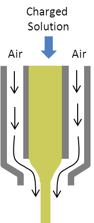
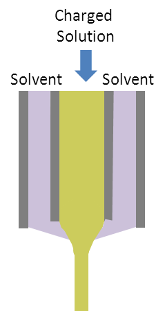
Fig 1. Left. Schematic of electroblowing where air jet is used to facilitate electrospinning jet initiation. Right. Solvent jacket surrounding the inner solution to prevent premature solidification during electrospinning.

Solidification of the spinning material at the tip of the nozzle is often a problem when electrospinning using highly volatile solvent. In some cases, the solidified material obstructs the nozzle opening and stops the spinning process. The solidified materials may also deposit on the collector as unwanted debris. With a co-axial nozzle, the solution to be electrospun may pass through the core nozzle while a second component for facilitating steady jet is added on the outer orifice. Air jet has been shown to facilitate electrospinning jet initiation and this will also facilitates continuous electrospinning by ensuring continuous movement of the jet away from the nozzle.

Another method is to introduce a solvent through the outer orifice during electrospinning which prevents premature drying of the material at the nozzle tip. This is particularly useful when the solvent is highly volatile or when the solution concentration is very high. Yu et al (2011) demonstrated that at 30% (w/v) polyvinylpyrrolidone (PVP), the solution tends to solidify into a cylindrical column of semi-solid at the tip of the nozzle during electrospinning. However, introducing N,N-dimethylacetamide (DMAc) through the outer orifice allows for continuous electrospinning of PVP at the same concentration. The same method has been demonstrated on electrospinning of Eudragit L-100 in ethanol/ N,N-dimethylacetamide (DMAc) using the co-axial nozzle [Yu et al 2014]. The resultant fiber diameter is also much smaller than those from single orifice nozzle tip with a rounded cross-section. The solvent introduced to the surface of the electrospinning jet on the onset may have allowed a smoother mass transfer of the solvent from the inner core to the surface.

Left. Conventional electrospinning using single solution and single axial nozzle. Center and right. Electrospinning with a coaxial nozzle with a sheath solvent to stabilize the electrospinning jet. [Yu et al 2014 Journal of Nanomaterials, vol. 2014, Article ID 967295, 8 pages, 2014. doi.org/10.1155/2014/967295. This work is licensed under a Creative Commons Attribution 3.0 Unported License.]

One of the parameters influencing the quality of the fibers fabricated using this setup is the flow rate of the sheath fluid. Yu et al (2012) demonstrated the effect of varying the flow rate of the sheath fluid comprising of a mixture of acetone, DMAc, and ethanol (4:1:1 by volume) for electrospinning of ketoprofen-loaded cellulose acetate. At optimal sheath fluid flow rate, the fibers demonstrated more homogeneous structure, smaller diameters and narrower diameter distribution. However, when the sheath fluid flow rate is too high, the fibers start to show beads and clumps. This is likely to be caused by excessive sheath fluid that is still wet after deposition. It is also suggested that the excess sheath fluid may form globules along the electrospinning jet and local mixing with the core solution will result in beads formation [Yu et al 2013].

Using a solvent fluid flowing through the sheath in co-axial setup often resulted in a smaller electrospun fiber diameter compared to a single orifice setup. The primary reason for this is probably the delayed solidification of the electrospinning jet which gave it more time to be elongated. Without a solvent sheath, solidification of the skin will initiate upon exposure to the air and it will take more force to stretch the rapidly stiffening jet. However, with delayed solidification, the same force will yield a greater elongation. Zhou et al (2019) showed that with an increasing voltage, the fiber diameter gets smaller. This is because higher voltage translate to greater elongation force.

Having the electrospinning solution and its nozzle to be encapsulated within an outer sheath nozzle and solvent has been recommended for electrospinning of solution which is highly conductive or very low conductivity. For a highly conductive polymer solution, it is not able to sustain the electric field tangential to the fluid surface due to high recombination rate. On the other hand, a solution with very low conductivity is not able to transfer the induced ions in the fluid to the surface. For both cases, electrospinning will not proceed. Angammana and Jayaram (2010) hypothesized that using an outer sheath nozzle providing a suitable solvent will provide the necessary electrified fluid to initiate electrospinning. Using sodium alginate and RTV615 silicon rubber to represent highly conductive solution and poor conductive solution respectively, they were able to form the Taylor cone at the nozzle tip. However, they were only able to produce droplets instead of fibers, possibly due to the low molecular weight. Further studies are necessary to verify this method.

It may not be necessary to use a solvent as a sheath fluid to facilitate electrospinning. Wu et al (2016) used NaCl solutions for electrospinning a core solution of Eudragit L100 (EL100) dissolved in N,N-dimethylacetamide (DMAc). Without the sheath fluid, clogging of the solution was observed at the tip of the nozzle. Although EL100 is not soluble in water, the use of NaCl solution is still able to prevent clogging of the tip. In agreement with other results, increasing the sheath fluid flow rate reduces the diameter of the fibers. At a sheath to core fluid flow rate ratio of 0.2, the diameter of the fibers were brought down to 0.46 µm from an initial diameter of 1.4 µm (without sheath fluid). Further increase in the flow rate resulted in beaded fibers.

Published date: 29 May 2014
Last updated: 06 August 2019

Comments
[+]


Google Ad.