The ease of coating a layer of nanofiber on most substrates allows nanofibrous tubes to be constructed by depositing the fibers on a rod template. This method has been shown to be sufficiently versatile to construct fibers with varying orientation and is probably the most widely used method of constructing nanofibrous tube. A common difficulty of using this method is the removal of the rod from the coated fibers especially when the rod has been rotated at high speed or the fibrous coating is not sufficiently thick. High speed rotation of the rod during fiber collection will cause the fibers to be tightly wrapped round it making rod removal difficult. Where the coating is thin, the wall of the tube may crumble during the rod removal.
Randomly oriented nanofibrous tube
In electrospinning, fibers are deposited or coated on a suitable substrate which over time, build up a thick layer of fibers. To generate a nanofibrous tube, one of the simplest methods is to collect the fiber on a metal rod of suitable diameter. When the metal rod is rotating around its longitudinal axis at low speed, the fibers are deposited in a random manner.
For a simple lab-based setup, a motor with an adjustable vice chuck is most appropriate as this allows rods of various diameters to be used and to ensure that the center of rotation of the rod is along its longitudinal axis. An earthed wire may be used to touch the rotating metal rod for better grounding.
Nanofibrous tube with fibers oriented along the circumference
High speed rotating collector (Read here) is commonly used to construct aligned nanofiber membranes. However, to construct a tube consisting of fibers aligned along its circumference, this method is usually inadequate. This method requires the rotation speed on the surface of the collector to match or exceed that of the spinning jet. For a small diameter rod, the rpm (revolution per minute) needs to be very high to achieve the same surface rotation speed compared to a much larger diameter mandrel.
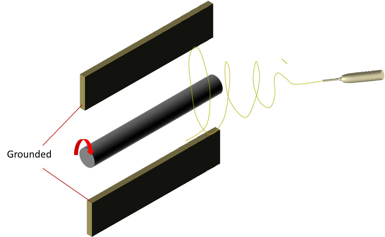
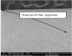
Apart from mechanical rotation, modification of the electric field offers an alternate way of achieving fiber alignment. However, since the objective is to construct a tubular structure, a rotating rod is still necessary and it provides a complementary force for fiber aligning. Taking advantage of the small diameter of the rod, a guiding electrode (Read here) placed behind the rod is able to exert an orientation preference to the spinning jet. This has been shown to significantly increase the alignment of the collected fibers on the rod (Teo et al 2005). Another hybrid electric-field and mechanical rotation method is to combine parallel collector electrodes setup with a rotating rod between them. This has been shown to be capable of constructing circumferentially aligned fibrous tube when the rotation speed is sufficiently high (1000 rpm for rod diameter of 4 mm) [Wang et al 2014].
Nanofibrous tube with fibers oriented parallel to the rod
To construct a nanofibrous tube with the fibers aligned in the longitudinal axis of the rod, a modification of the parallel electrode concept may be used. By positioning two conical shape electrodes in series with the apex point towards each other, fibers have been shown to deposit across the gap while forming a lumen in the middle [Jana 2012]. Such a tube may have significant potential in peripheral nerve repair where the aligned fibers may serve as contact guidance to accelerate neurite extension across the gap. Another advantage of this setup is that the tube can be easily removed from the collection points with minimal disruption to the fiber orientation.
Nanofibrous tube with fibers oriented in a diagonal direction
Tube consist of fibers oriented either in the circumferential or longitudinal axes will exhibit mechanical weakness when the force application is orthogonal to the orientation of the fibers. This may result in unfavorable mechanical characteristic in applications where the force may be applied from different directions. The ability to control the orientation of the fiber beyond the principal axes will allow greater control in the mechanical characteristic of the resultant tube. With the use of guiding electrodes, the electrospinning jet can be encouraged to follow a relative direction which in turn can be used to create tubes with fibers oriented in the preferred direction. This has been successfully demonstrated by Teo et al where diagonally oriented fibers have been deposited on a rod using a setup base on the concept [Teo et al 2005].
Nanofibrous tube with complex fiber orientations
Deposition of electrospun fibers have been shown to be influenced by the electric field profile and the surface topography of the collector which gives rise to patterned membranes. Such patterned membranes are known to demonstrate mechanical properties [Gibson et al 2004] and cell response [Vaquette et al 2011] that differs from nonwoven membranes. To construct nanofibrous tube with complex fiber orientation, the method used for fabricating patterned membrane has been employed to construct electrospun tubes with unique surface topography [Zhang et al 2008]. Similarly, the effect of parallel electrodes concept has also been used to create tubes with sections of randomly oriented/aligned fibers and orthogonal aligned fibers in between. This can be achieved by using spiral tubes as shown in the figure below or rods with circumferential protrusions.
Nano-solenoid
The diameter of the rods used in the construction of tubular structures is typically in the range of a few millimetres to mimic the dimension of small diameter blood vessels or neural tube. However, the same technique has been used to construct nano-solenoid and micro-tubular nanofibrous structure. Zhang et al (2013) used carbon fiber with diameter of 7 µm as the collector. This is rotated at high speed of up to 8000 rpm to wound fibers around it during electrospinning. To direct the electrospinning jet, an aluminium plate with an opposing negative high voltage was placed behind the collector. Zhang et al (2013) was able to collect fibers arranged in the form of solenoid around the carbon firber from polyvinylpyrrolidone(PVP), zinc acetate/PVP composite (ZnAc/PVP) and as- electrospun 0.5Ba(Zr0.2Ti0.8)O3-0.5(Ba0.7Ca0.3)TiO3 (BZT-BCT) nanofibers.
Published date: 23 July 2013
Last updated: 20 October 2015
▼ Reference
-
Gibson P, Schreuder-Gibson H. Patterned Electrospray Fiber Structures. INJ Summer 2004; 37.
Open Access
-
Jana S. Designing of Chitosan-Based Scaffolds for Biomedical Applications. PhD Thesis. University of Washington 2012.
Open Access
-
Teo W E, Kotaki M, Mo X M, Ramakrishna S. Porous tubular structures with controlled fibre orientation using a modified electrospinning method. Nanotechnology 2005; 16: 918 - 924.
-
Vaquette C, Cooper-White J J. Increasing electrospun scaffold pore size with tailored collectors for improved cell penetration. Acta Biomaterialia 2011; 7: 2544.
-
Wang Y, Shi H, Qiao J, Tian Y, Wu M, Zhang W, Lin Y, Niu Z, Huang Y. Electrospun Tubular Scaffold with Circumferentially Aligned Nanofibers for Regulating Smooth Muscle Cell Growth. ACS Appl. Mater. Interfaces 2014; 6: 2958.
-
Zhang D, Chang J. Electrospinning of Three-Dimensional Nanofibrous Tubes with Controllable Architectures. Nano Letters 2008; 8: 3283.
-
Zhang D, Meng L, Xu Q, Bai S, Yang Z, Qin Y. Electrospinning multi-layered nano-solenoid and reticular micro-tubular structure on a microfiber. Materials Letters 2013; 98: 153.
▲ Close list