Basic electrospinning is based on application of charges to a solution under an electric field to produce fibers without any other external forces. However, differing solution spinning behavior and output requirements have led to the introduction of external forces to compliment the electro-repulsive forces of the electrospinning jet. A commonly used complimentary external force application is through the use of gas jet surrounding the electrospinning nozzle. With the additional stretching force provided by the gas jet, small diameter fibers have been produced [Lin et al 2009]. It has even been shown to influence poly(vinylidene fluoride) crystal structures [Lin et al 2009]. Although it is the same force application, the primary intention of using electroblowing varies. In general, electroblowing is used for the following purpose,
- Increase productivity
- Facilitate jet initiation
- Maintaining spinning jet continuity
- Directing of electrospinning jet
- Increase speed of fiber deposition
Electroblowing is similar to melt blowing in that both process uses gas jet to aid in the extension of the spinning jet. However, melt blowing uses only the drawing force from the gas jet to stretch the fiber while electroblowing relies more on electrostatic repulsion to stretch the fiber with the gas jet facilitating solution drawing at the initial phase only. In a study by Chen et al (2016), the diameter of melt blown fibers were compared with those from melt blown with electrospinning. For the latter fibers, the melt blowing die was connected to a high voltage power supply to introduce electrical charges as in electrospinning. Their results showed that with electrospinning incorporated to the melt blowing, the fiber diameter is consistently less than 1 µm while the melt blown only fibers ranges from 1.2 µm to 2.8 µm. The reduction of fiber diameter when a high voltage was applied is more than 60%.
Electroblowing is also effective in reducing fiber diameter when used with conventional electrospinning setup. Using electroblowing with electrospinning parameter adjustments, Zhang et al (2018) was able to bring the fiber diameter to below 100 nm. In their electrospinning of polyvinyl alcohol/poly(3,4-ethylenedioxythiophene)-poly(styrenesulfonate) (PVA/PEDOT:PSS), conventional electrospinning with applied voltage of 20 kV and tip to collector distance of 15 cm, the resultant fiber has a diameter of 263 nm. By using high pressure airflow assisted electrospinning or electroblowing, modifying the setup with negative 35 kV voltage applied to the nozzle and a positive 35 kV voltage applied to the collector (a potential difference of 70 kV), and increasing the tip to collector distance to 120 cm, they were able to reduce the average fiber diameter to 68 mm. Without the airflow directing the flight of the electrospinning jet, the fibers may not reach the collector given the large distance between the tip and collector.
In conventional electrospinning, the production rate is limited by the speed at which the solution is ejected from the tip of the nozzle. When the feed rate is too high, the solution may start to drip off from the tip of the nozzle instead of being drawn off [Liu et al 2009]]. With electro-blowing, the flow rate can be increased significantly as the blowing air is able to draw the solution from the nozzle while generating a strong initial stretching force. Liu et al (2009) was able to increase the production rate of polyvinyl alcohol by 11 times over conventional electrospinning using electroblowing with very little increase in the fiber diameter (electroblown fiber diameter of 231 nm).
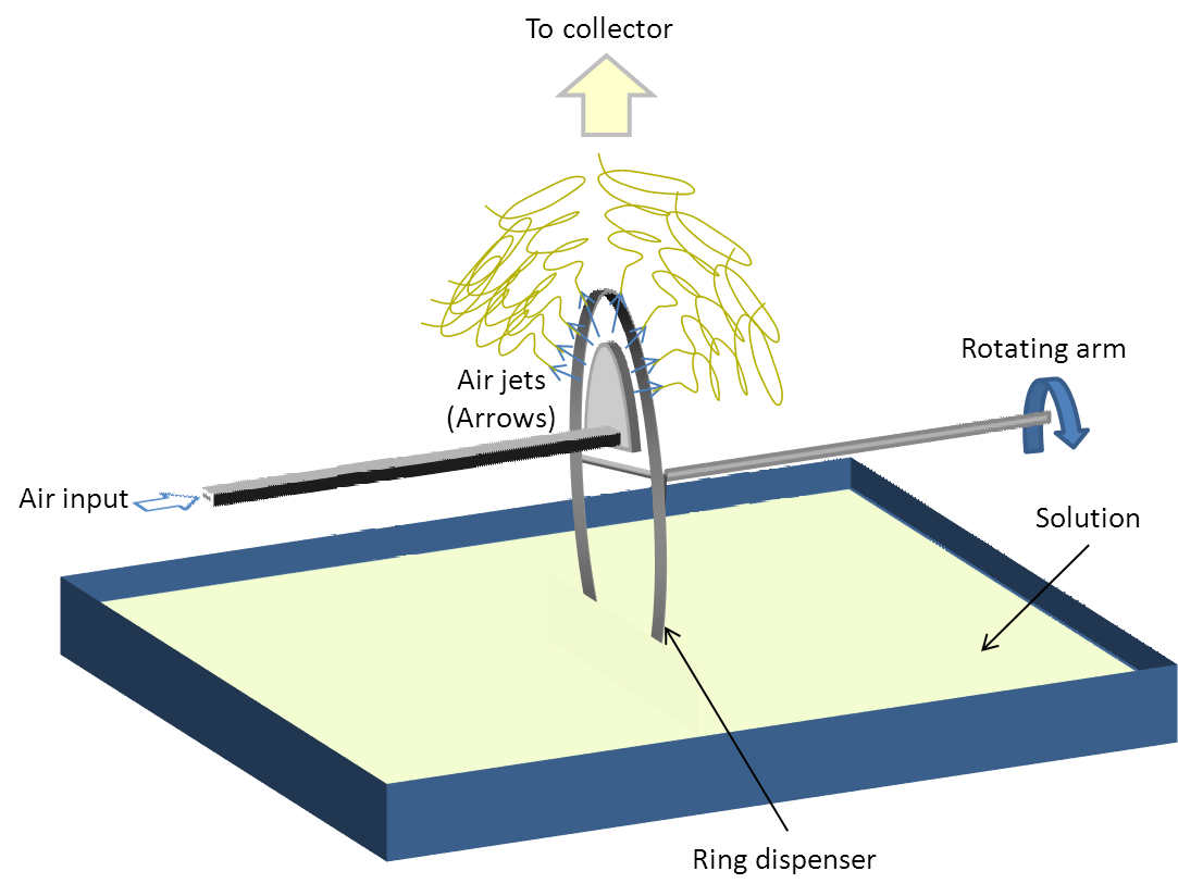
Using airflow to increase the production rate of electrospinning has also been tested on needle-less electrospinning setup. Wang et al (2014) tested the effect of airflow on the production of electrospun fibers from a ring that rotates and dip into a solution reservoir (See figure 2 for illustration). Comparing the fiber production rate at different air flow rates, it was found that at lower air flow rate, the fiber production is lower than spinning without air flow. It was only at higher air flow rate that the fiber production rate is increased. At lower air flow rate, the solution coating on the circumference of the ring may be blown dry thus reducing the amount of available solution for jet initiation. At high air flow, the blowing air is sufficiently strong to stretch the polymer from the ring edge thereby facilitates jet initiation.
In a multiple nozzle electrospinning setup, the use of electroblowing helps to reduce the differences in electrospinning conditions of the jets coming from the inner nozzles and the outer nozzles. In multiple nozzle electrospinning setup, the inner nozzles experience a reduced electric field strength, reduced traveling distance of the electrospinning jet and higher residual charges at the center collector region. These will result in higher diameters in the fibers collected in the center compared to the edges. The addition of sheath gas helps to reduce the difference in the electrospinning conditions by providing a uniform drawing force from the sheath gas across all the nozzles, dispersing the residual charges from the collected fibers and restricting the area which the electrospinning jet can travel across all the nozzles. Studies by Zheng et al showed that a higher sheath gas pressure significantly reduces the differences in the fiber diameters from the fibers collected at the center and the edges.
Using an air or gas jet to facilitate drawing of the solution droplet with the application of high voltage has been shown to be effective in the fabrication of smooth fibers when standard electrospinning only yield beaded fibers [Um I C et al 2004, Peng M et al 2008]. It is particularly useful in solution which is highly viscous and application of high voltage only is unable to overcome the surface tension of the solution. This method has been shown to be non-material specific and has been used successfully to fabricate other materials such as poly(ether sulfone) [Lin Y et al 2008] and poly(methyl methacrylate)/tetraethoxysilane solution [Peng M et al 2008]. In an extension of electro-blowing, heated gas may be used instead to reduce the viscosity of the solution and encourage greater elongation of the fiber. This has been demonstrated to be more effective in reducing the fiber diameter than increasing the solution temperature [Ahmad et al 2012].
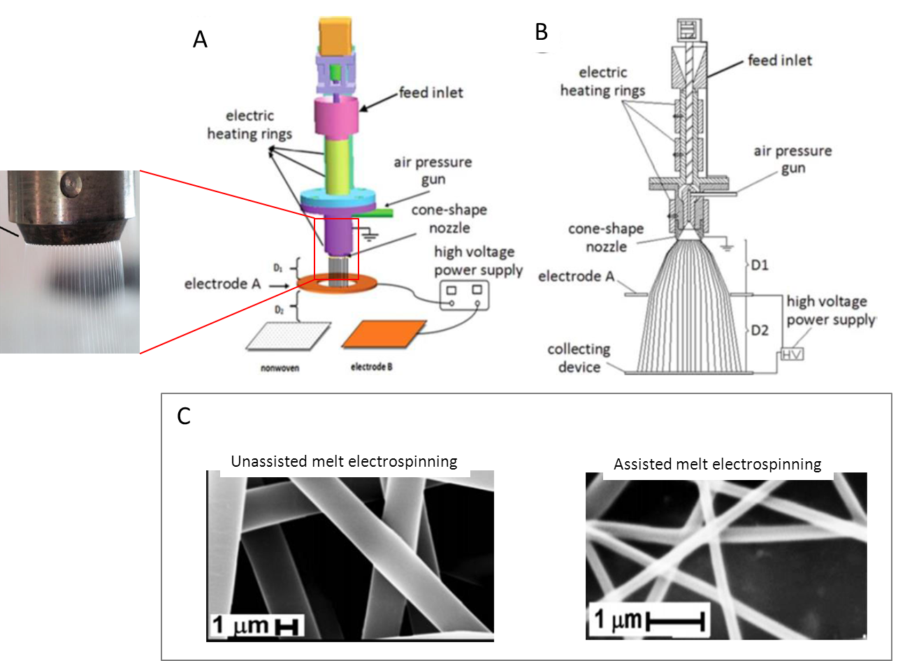
A development in mass production melt electrospinning is to use hot air to facilitate fiber drawing. In the setup by Bubaikir et al (2014) as shown below, the electrode supplying the high voltage is separated from dispensing unit to prevent interference of the high voltage with the heating element and dispensing unit. The molten polymer was ejected from the nozzle and passes through the charged ring electrode which initiated the electrospinning process. Using polypropylene, the hot air assisted electrospinning was able to reduce the fiber diameter from a range of 1 - 2 µm to 0.2 - 0.8 µm [Bubaikir et al 2014]. This setup was able to achieve a melt flow rate of 12 kg/h. Assuming no loss in the raw material, this yield is much higher than any other reported electrospinning mass production.
With the gas jet constantly applying a shearing force on the nozzle tip, building-up of solution at the tip can be prevented. This is particularly useful for viscous solutions such as hyaluronic acid [Um et al 2004], as electroblowing is able to facilitate jet initiation and to maintain a continuous electrospinning jet so that high quality, uniform fibers can be produced.
A seldom used application of electroblowing is in the directing of electrospinning jet and increasing the speed of fiber deposition. In the presence of a gas jet, the electrospinning jet is being accelerated in a singular direction towards the collector surface despite the conical evolution of the jet due to the electrostatic charges. The reduced flight time pushes the electrospinning jet to deposit on the collector before the conical path expands. This characteristic of electroblowing makes it favorable for applying medical cyanoacrylate glue on a wound for rapid closure. Jiang et al (2014) successfully demonstrated such an application for rapid hemostasis in liver resection. The electrospun coating was able to arrest blood seepage from the wound. Lv et al (2016) showed that with electroblowing of N-octyl-2-cyanoacrylate, the deposition width can be narrowed to 4 mm when the electrospinning distance was 2 cm. As the electrospinning distance increases, so was the fiber deposition width. At a distance of 6 cm, the deposition width was increased to 12 mm. This was still much smaller than conventional electrospinning which typically has a deposition width of 50 mm or more. With such narrow width, they were able to demonstrate sealing of dural defects while avoiding tissue adhesion. When electroblowing is used with near field electrospinning, this increases the precision and accuracy of the fiber deposition. However, unlike most near field electrospinning setup, the distance between the nozzle tip and collector cannot be too close or there will be air turbulence from the blowing air bouncing off the solid substrate. Jiang et al (2018) showed that the optimum distance for assisted airflow near field electrospinning was 2 mm for polyethylene oxide (PEO) solution. Both precision and accuracy were improved with assisted airflow. When combined with optimised collector velocity, positioning errors of less than 5% has been printed for complex patterns.
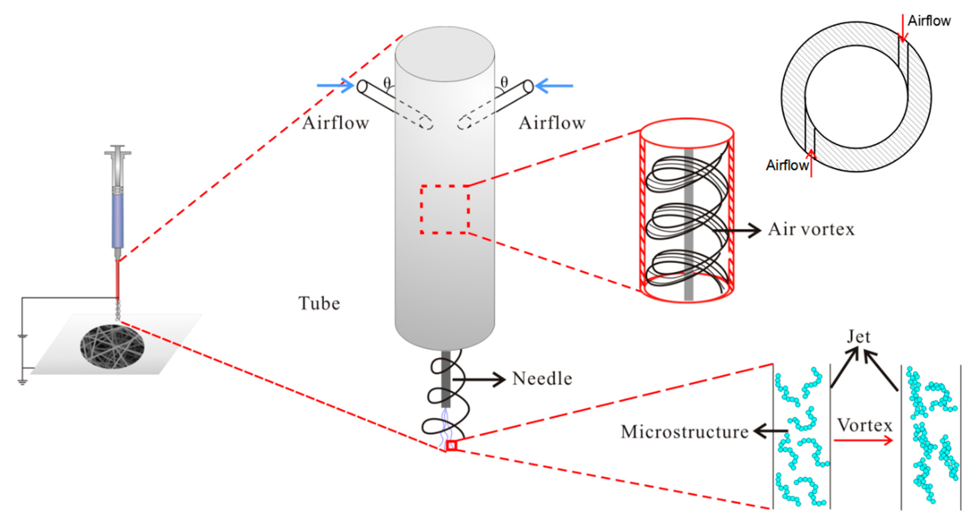
A further modification of electroblowing is to change the direction of the moving air jet such that it creates a wind vortex around the electrospinning needle outlet and towards the collector. In the study of this setup by Tian and He (2020), increasing air vortex speed reduces fiber diameter and diameter distribution. Increasing air vortex speed was also found to result in greater adhesion between fibers on the constructed membrane. This is probably due to faster fiber deposition which reduces the time needed for the fiber to dry sufficiently before the next fiber impacts it. The ultimate tensile strength of the collected electrospun membrane was also found to increase with higher air vortex speed. This is probably due to greater adhesion between the fibers which have a strengthening effect on the membrane. More studies are needed to determine whether there is a significant advantage of using a vortex airflow compared to conventional linear airflow of electroblowing.
Published date: 23 July 2014
Last updated: 30 March 2021
▼ Reference
-
Ahmad B, Stride E, Stoyanov S, Pelan E, Edirisinghe M. Electrospinning of Ethyl Cellulose Fibres with a Heated Needle and Heated Air Using a Co-axial Needle: a Comparison. Journal of Medical and Bioengineering 2012; 1: 1
Open Access
-
Bubakir M M, Li H, Wu W, Li X, Ma S, Yang W. Applications of web produced by hot air assisted melt differential electrospinning method. IOP Conf. Series: Materials Science and Engineering 2014; 64: 012052.
Open Access
-
Chen T, Sun H M, Wu L L. A Melt Blowing-electrospinning approach to fabricating Nanofibers. Thermal Science 2016; 20: 1010.
Open Access
-
Jiang J, Long Y Z, Chen Z J, Liu S L, Huang Y Y, Jiang X, Huang Z Q. Airflow-directed in situ Electrospinning of a Medical Glue of Cyanoacrylate for Rapid Hemostasis in Liver Resection. Nanoscale 2014Article in press
-
Jiang J, Wang X, Li W, Liu J, Liu Y, Zheng G. Electrohydrodynamic Direct-Writing Micropatterns with Assisted Airflow. Micromachines 2018; 9: 456.
Open Access
-
Lin Y, Yao Y Y, Yang X Z, Shen L M, Li R X, Wu D C. Effect of gas flow rate on crystal structures of electrospun and gas-jet/electrospun poly(vinylidene fluoride) fibers. Chinese Journal of Polymer Science 2009; 27: 511.
-
Liu W, Yao Y, Lin Y, Wang B, Luo Y, Li N, Zhang Q, Wu Y, Niu A. Electrospinning Assisted by Gas Jet for Preparing Ultrafine Poly(vinyl alcohol) Fibres. Iranian Polymer Journal 2009; 18: 89.
Open Access
-
Lv F Y, Dong R H, Li Z J, Qin C C, Yan X, He X X, Zhou Y, Yan S Y, Long Y Z. In situ precise electrospinning of medical glue fibers as nonsuture dural repair with high sealing capability and flexibility. International Journal of Nanomedicine 2016; 11: 4213.
Open Access
-
Peng M, Sun Q, Ma Q, Li P. Mesoporous silica fibers prepared by electroblowing of a poly(methyl methacrylate)/tetraethoxysilane mixture in N,N-dimethylformamide. Microporous and Mesoporous Materials 2008; 115: 562.
-
Tian D, He J H. Control of Macromolecule Chains Structure in a Nanofiber. Polymers 2020; 12: 2305.
Open Access
-
Wang X, Lin T, Wang X. Use of airflow to improve the nanofibrous structure and quality of nanofibers from needleless electrospinning. Journal of Industrial Textiles 2014. Article in press DOI: 10.1177/1528083714537100.
-
UM IC, Fang D, Hsiao B S, Okamoto A, Chu B. Electro-spinning and electro-blowing of hyaluronic acid. Biomacromolecules 2004; 5: 1428.
-
Zhang Q, Wang X, Fu J, Liu R, He H, Ma J, Yu M, Ramakrishna S, Long Y. Electrospinning of Ultrafine Conducting Polymer Composite Nanofibers with Diameter Less than 70 nm as High Sensitive Gas Sensor. Materials 2018; 11; 1744.
Open Access
-
Zheng G, Jiang J, Wang X, Li W, Liu J, Fu G, Lin L. Nanofiber membranes by multi-jet electrospinning arranged as arc-array with sheath gas for electrodialysis applications. Materials & Design 2020; 189: 108504.
Open Access
▲ Close list