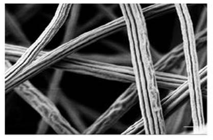
Electrospun fibers are often described as having a circular cross section with a smooth surface. Although such physical structures are more commonly encountered, electrospun fibers with different cross-section shape and surface textures have been reported. Such alternate physical characteristic is often due to the solvent-solute distribution during vaporization and phase transitions in the polymer solution. However, the effect of charges on electrospinning jet has also been brought forward as an explanation for producing certain fiber cross-section shape [Li et al 2011].
The presence of grooves and other surface textures on the electrospun fiber may influence the physical characteristics of the resultant fiber and membrane due to higher surface area and surface roughness respectively. Hence, the electrospinning setup may also be deliberately modified to encourage the formation of grooves on the fibers.
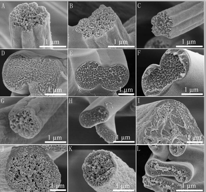
Flat ribbons or ribbons with two tubes (dumbbell shape) are formed when a skin layer forms during electrospinning which subsequently collapsed. Such ribbons have been found from electrospinning various polymers,
-
10% poly(ether imide) in hexafluoro-2-propanol [Koombhongse et al 2001]
-
30% polystyrene in dimethylformamide [Koombhongse et al 2001]
-
20 wt% Nylon 11 in formic acid [Dhanalakshmi et al 2008]
-
Polyvinyl alcohol in water [Koski et al 2004]
Using a more volatile solvent for electrospinning has been shown to result in ribbon/flat fibers. Celebioglu and Uyar (2011) demonstrated this effect when they electrospin cellulose acetate with dichloromethane (DCM) and acetone mixture. They hypothesized that rapid vaporization of the solvent within the electrospinning jet leads to the formation of a skin layer which later collapsed to form ribbons. When the more volatile dichloromethane was replaced with less volatile N,N-dimethylacetamide (DMF), round fibers were produced. Similar results were demonstrated by Gopal et al (2010) with electrospun polysulfone where ribbon shaped fibers were produced when DCM was used as the solvent but round fibers were produced using less volatile DMF and pyridine. However, as seen in the list of examples above, solvent volatility is not the only cause of ribbon fiber formation.
Formation of ribbons is not just dependent on the polymer and solvent combination but also on the concentration. Dhanalakshmi et al (2008) showed that 10 wt% Nylon 11 in formic acid gave fiber with circular cross section but increasing the concentration to 20 wt% produces flat ribbon fibers. Koski et al (2004) also reported flat ribbon fibers when the concentration of polyvinyl alcohol (PVA) was high or higher molecular weight of PVA was used while lower concentration and molecular weight produces circular cross-section fiber. From reported studies, ribbon cross-section fibers are generally formed when higher viscosity solution is used. A higher viscosity may favor a more rapid solidification of the electrospinning jet at its surface resulting in the formation of a stable skin layer. Similarly, electrospinning at elevated ambient temperature may also favor the formation of a stable skin layer. Amiraliyan et al [2009] showed that when the temperature increases, silk nanofiber cross-section transformed from round to ribbon-like shape. When the solvent migrating through the core of the electrospinning jet to the surface is insufficient to affect the skin layer, a hollow core starts to form which subsequently collapsed to form flat ribbons. Dumbbell shape fibers are formed when the collapsing skin pushes the remaining solution in the fiber core to both ends prior to complete vaporization of the solvent.
Another factor that contributes to ribbon fiber formation is the solution feed rate with higher feed rate giving ribbon or flat fibers. Initially with a lower feed rate, the fiber cross section is round. As the feed rate increases, the fiber diameter increases while maintaining a round cross section. Above a certain feed rate, the cross section of the fiber switches from round to flat or ribbon shape. This has been observed in electrospun chitosan/polylactide blends when the feed rate was increased to 1.5 ml/h [Chen et al 2014]. The inability of the thin wall to support the increasing fiber diameter eventually causes it to collapse and form flat and ribbon fibers.
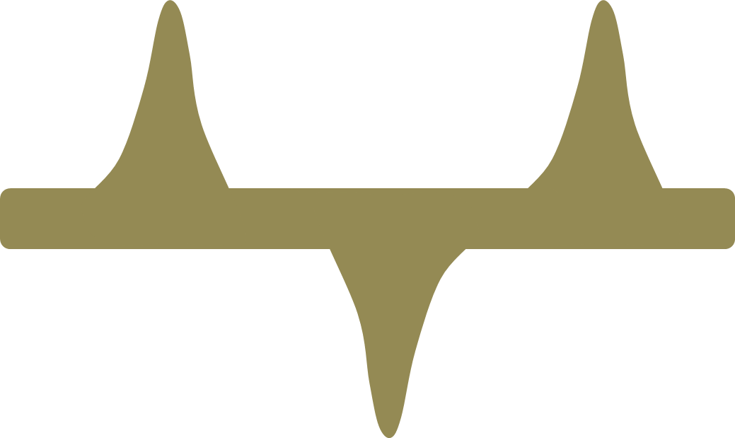
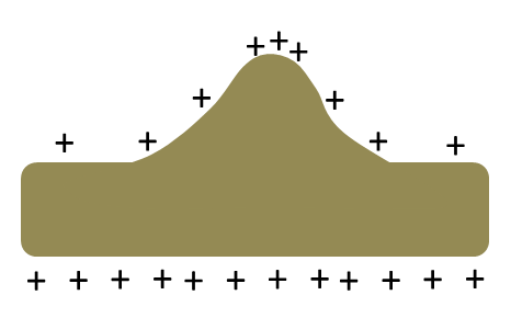
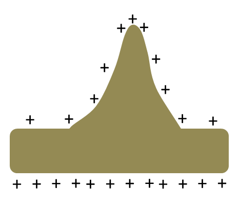
Given an ideal set of electrospinning condition, barbed fiber may be produce from a low concentration/shear viscosity and relatively low-conducting, almost dielectric solution [Holzmeister et al 2010]. Since electrical charge repulsive force within the electrospinning jet is non-directional, it will be exerted in all directions and not necessarily in the direction of the jet path. When there is a slight undulation on the side of the electrospinning jet, a momentary increase in the charges may cause the side undulation to grow due to charge-charge repulsion especially for a dielectric solution under the influence of the external electric field. When the charge relaxation (low conducting, almost dielectric solution jets) time is more than the hydrodynamic time of bead formation, barbs start to form from the side of the fiber [Holzmeister et al 2010]. As the concentration increases, the diameter of the fiber and the barbs increases with the increase of the later higher until the viscosity is too high for barbs formation. At the other extreme, too low a viscosity results in beads formation as instability dominates [Holzmeister et al 2010]. Holzmeister et al (2010) describes a model on the formation of barbs from electrospinning of purified polyvinylalcohol in double distilled water.
Twin fibers where two fibers are connected along its length have been produced using electrospinning. Instead of skin formation followed by its collapse, Li et al (2011) suggested a different mechanism for the formation of Cerium (III) nitrate/poly(vinylpyrrolidone) (Ce(NO3)3/PVP) twin fibers. Li et al (2011) hypothesized that charge repulsion towards the ends of the electrospinning jet at its radial direction causes the formation of twin fibers. With sufficient repulsion, the twin fibers may split apart to form two separate fibers. Otherwise, the repulsion is only sufficient to form two fibers that are connected down its length. Zeng et al (2012) also produced twin fibers using drug loaded poly(l-lactide) and poly(l-lactide-co-glycolide). With increasing concentration of rifampin, the number of twin fibers increases. However, with paclitaxel added, only single circular fibers were produced regardless of concentration added. Comparison of the conductivity of the polymer/drug solution showed no apparent differences. A difference between the drugs is that rifampin is amphipathic while paclitaxel is hydrophobic. It is yet unclear whether this difference accounts for the influence in twin fiber formation. Goktas 2008 electrospin a blend of polystyrene and butyl rubber and produced twin and dumbbell shaped fibers. It may be possible that the hypothesis of skin formation applies to twin fiber formation as well and whether twin or dumbbell shaped fibers are formed depends on solvent migration and solution phase separation. The difference in fiber shape when rifampin or paclitaxel is added may be due to the influence of the drugs on skin formation. Paclitaxel being hydrophobic may retard skin formation as it maintain an even distribution of the solvent molecules across the cross-section of the fiber during solvent vaporization.
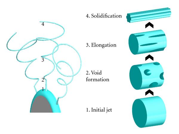
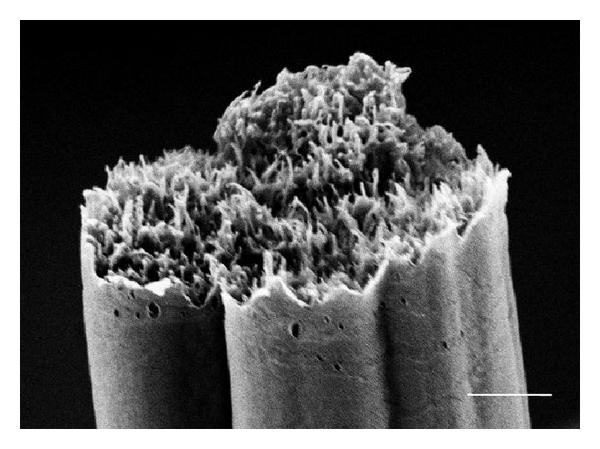
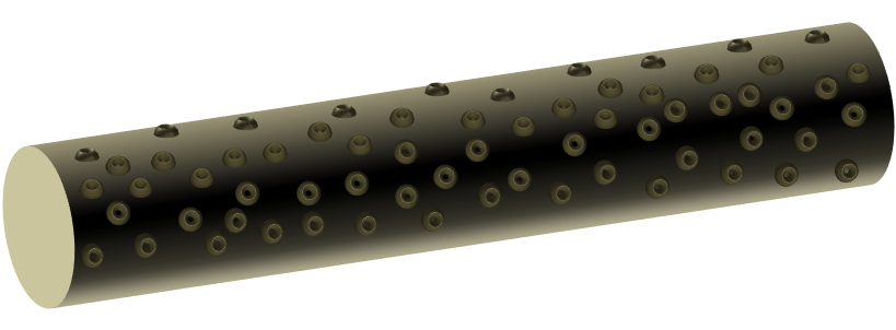
Fibers with deep grooves running along its length have been reported from electrospinning. Huang et al (2012) constructed such fibers using 10% polystyrene in acetone/dimethyl formamide mixture. They attributed the formation of the grooves to void formation at the initial spinning surface which elongates as the jet stretches thereby forming the grooves. Voids or pores on electrospun fiber surface have been observed and it is possible that they may play a part in the formation of the grooves. However, it seems unlikely that stretching of the voids lead to grooves running along the full length of the fiber. An alternative possibility is that skin formation and the presence of elliptical voids contributed to the formation of the grooves. With skin formation, the skin will naturally collapse inwards to fill in the empty lumen. With the presence of elliptical voids, it forms a line of weakness for preferential collapse of the skin. Voids distributed around the fiber circumference cause the fiber surface to fold inwards in all direction thereby creating the grooves. Evidence on the formation of pores under the influence of solvent evaporation was demonstrated using cellulose acetate butyrate in acetone/DMAc (2:1) mixture [Huang et al 2011]. Observation on the formation of void was done using liquid film. In an enhanced convective condition where the solvent evaporation rate is increased, faster void formation was observed. Sufficient time should be given for solvent evaporation to form parallel groves along the length of the fibers. When the distance between the electrospinning tip and collector is short (eg. 14 cm), fibers without parallel groves were obtained instead. When the solvent is being replaced with higher boiling point solvent, less distinct grooves on the fibers were constructed. A higher polymer molecular weight and concentration is also preferred to obtain grooved structure. Other polymers that have been successfully electrospun to form fibers with parallel grooved structure includes poly(vinylidene fluoride-co-hexafluoropropene) although polycaprolactone fiber fails to show the grooved structure under similar parameters [Huang et al 2011]. Liu et al (2015) conducted a comprehensive study on the effect of solvent system on the formation of polystyrene fiber shape. Using a single solvent, fiber with surface structure such as wrinkled beads, smooth fibers and surface pores were electrospun. To obtain additional surface structure such as single groove and multiple grooves on the fiber, binary solvent systems need to be used. Further, it was pointed out that there must be sufficient differences in the evaporation rate between the two solvents to initiate groove formation. Zaarour et al (2018) proposed that humidity and a non-solvent of the polymer are needed to form surface textures on the fibers. In many cases, water is a non-solvent and high humidity encourages water droplets to condensate on the electrospinning jet and drives the formation of secondary surface morphology. Using polyvinylidene fluoride (PVDF) in acetone, dimethyl formamide (DMF) and their mixture, they showed that the electrospun fibers will always be smooth at low relative humidity of 5%. It is only when relative humidity was raised to 25% where rough nanofiber surface started to appear. At 45% relative humidity, all the nanofibers exhibit textured surface regardless of solvent used. The surface texture may be rough, porous or groove. Porous surface nanofibers were produced where only acetone was used as the solvent. When there was a higher or equal ratio of acetone in a mixture with DMF, grooved surface texture was produced. For solvent of DMF only or higher ratio of DMF, smooth or rough surface nanofibers were produced. Zaarour et al (2018) suggested that grooved surface from acetone/DMF solvent mixture came from extension of pores. Since acetone, with its greater volatility encourages pore formation, but DMF with its lower volatility allows the semi-solid fiber sufficient mobility to stretch the pores and merge them into grooves. When there is higher ratio of DMF, the pores generated from evaporating acetone may be too shallow and dispersed to be connected to form grooves.
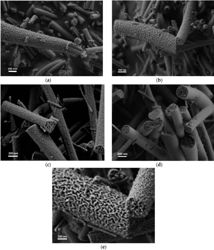
Having specific solvent-polymer pairs to produce electrospun fibers with longitudinal grooves may be very restrictive in the type of polymer available. Wang et al (2024) used a mixture of two immiscible polymers and coaxial electrospinning to produce fibers with longitudinal grooves after removing one of the polymers. Poly (ε-caprolactone) (PCL) and polyvinylpyrrolidone (PVP) was used in the coaxial electrospinning where the core was made of pure PCL and the outer shell made of PVP/PCL mixture. During electrospinning, the evenly dispersed PVP was stretched on the PCL fiber surface. Subsequent washing with ethanol was used to remove the PVP to give rise to PCL fibers with grooves.
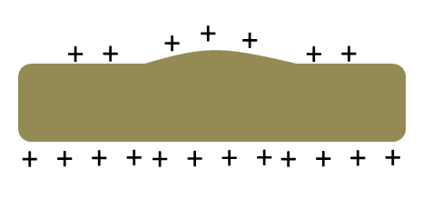
Pores both on the surface and at the subsurface level have been observed from electrospun fibers. Such formation is usually due to the electrospinning environment such as humidity and temperature and its influence on the solution. More information on pores on the surface level may be found here. Fashandi and Karimi (2012) found that using N,N-dimethylformamide (DMF) for preparing polystyrene solution, increasing humidity causes the formation of subsurface pores due to condensation and absorption water vapor into the electrospinning jet resulting in a binary mixture and subsequent phase separation. However, with increasing temperature, the miscibility zone expands and a higher humidity is required to initiate phase separation. The thickness of the smooth skin on the surface of polystyrene fibers from electrospinning polystyrene in DMF solution was found to be inversely proportional to the concentration of the solution. As a result smaller diameter fibers from lower solution concentration were found to have thicker skin layer compared to larger diameter fibers [Demir et al 2010]. Demir (2010) proposed a mechanism where polymer molecules concentrated on the surface boundary of the electrospinning jet. Such distribution may be due to capillary effect and charge repulsion and a low solution concentration allows greater movement of the polymer molecules to the surface resulting in a solvent rich core. Water vapor condensation and absorption of the water to the solvent rich core of the electrospinning jet initiates liquid-liquid phase separation. With higher solution concentration, greater chain entanglements between the polymer molecules prevented free movement thus only a thin skin is formed on the fiber surface due to liquid-liquid phase separation.
Huang et al (2024) showed that with cyanoethyl cellulose (CEC) blended into polyvinylidene fluoride (PVDF) solution for electrospinning, the resultant CEC/PVDF fibers showed significantly greater roughness with a large number of tiny spherical particles on their surfaces compared to pure PVDF electrospun fibers. It is likely that the presence of another polymer in the solution encourages more pronounced phase separation. In this case, CEC being more hydrophilic than PVDF may cause water condensing on the electrospinning jet to be retained on the surface for phase separation.
Using parameters including solvent vapor pressure, relative humidity, surface affinity for water and temperature, Zhang et al (2020) proposed an empirical model for the prediction of morphological features on the surface or bulk of electrospun fibers. Another criteria is that the polymer needs to be a non-water soluble polymer. An evaluation parameter in their equation is Cw, which measures the propensity for water condensation. When Cw >> 1, there is much water vapor condensation on the surface of the electrospinning jet. This will lead to the formation of peats, pore or phase separation either on the surface or the bulk of the polymer fiber. When Cw << 1, there is no water vapor condensation hence the polymer surface remains smooth. They hypothesised that with a less volatile polar solvent, water vapour that condensates on the fiber surface would have time to migrate into bulk and cause phase separation resulting in wrinkled fibers.
Instead of pores, protrusions or bumps have been observed on the surface electrospun polystyrene fibers. These were produced when N,N-dimethyl formamide (DMF) was used as the solvent for preparing the polystyrene solution and at high concentration (35 wt%) [Kim et al 2005]. A probable mechanism for the formation of these protrusions is solvent entrapment in the fibers which pushes against the surface after a skin layer has formed. Given the low vapor pressure of DMF and the larger fiber diameter (>5 µm), it is possible that solvents at the core of the electrospinning jet takes a longer time to migrate to the surface. Observation under optical microscope revealed submicron size bubbles inside the fiber [Kim et al 2005].
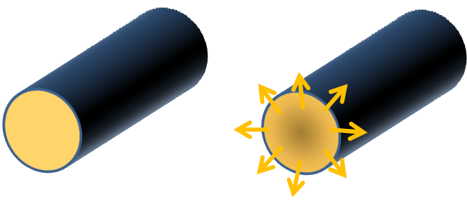
Electrospun hollow fibers have been fabricated without using coaxial electrospinning. Such fibers are mostly produced from sintering of inorganic precursor solution. Xia et al (2012) was able to generate hollow SnO2 nanofibers from sintering of electrospun polyvinylpyrrolidone (PVP)/Sn precursor solution. Observation of the polyvinylpyrrolidone (PVP)/Sn fiber under TEM showed two distinct phases along the length of the fibers with the Sn precursor at the fiber core. During sintering, Kirkendall effect causes movement of Sn precursor molecules through the oxide layer and the balancing flow of vacancies results in the formation of SnO2 at the surface and a hollow core. An et al (2013) showed with electrospun polyvinylpyrrolidone (PVP)/Nb-doped SnO2 precursor solution that heating rate influences the formation of solid or hollow fibers. At low heating rate of less than 1.25 °C/min, slow decomposition reaction gave rise to solid fibers while at heating rate 5 °C/min (500 °C), Sn ions and Nb ions decomposed from the core of the nanofiber and migrate to the surface where it reacts with atmospheric oxygen to form oxides thereby forming hollow fibers. Hollow LaFeO3 fiber has also been fabricated using electrospinning precursor of PVP/[La(NO3)3 + Fe(NO3)3] and sintering at temperature of 600 °C - 800 °C. It was mentioned that the average molecular weight and concentration of PVP had an influence on the formation of LaFeO3 hollow nanofibers [Dong et al 2009] although it has not been investigated in the research.
Formation of stable skin layer followed by solvent migration from the interior to the surface and vaporaization.
|
| Structure |
Proposed Mechanism |
Reference |
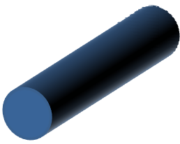
Solid circular cross-section
|
Steady diffusion of solvent throughout cross-section of fibers from the core to the surface. Uniform reduction of fiber diameter as solvent vaporizes until a solid core is formed. |
|
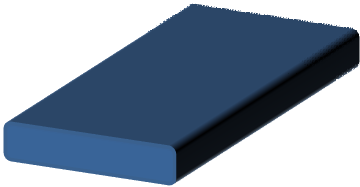
Flat/ribbon fiber
|
Stable skin formation and rapid vaporization of solvent results in a thin wall fibers that collapse |
Dhanalakshmi et al 2008 |
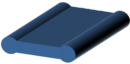
Dumbbell shape fiber
|
Stable skin formation and less rapid vaporization of solvent results in the wall collapsing in the middle. Vaporization rate is sufficient for substantial middle section to form thin walls that collapsed but insufficient to avoid material build-up at its ends |
Koombhongse et al 2001 |
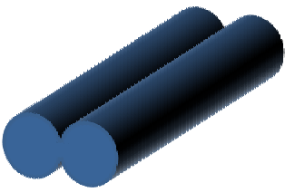
Twin fibers
|
Stable skin formation and less rapid vaporization of solvent results in the wall collapsing in the middle. Vaporization rate is only sufficient for the central part of the fiber to collapse. |
Zeng et al 2012 |
Fiber with longitudinal grooves
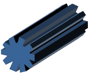
|
Voids forming lines of weakness along the skin causing preferential skin folding in that direction resulting in grooves. |
Huang et al 2012 |
Elishav et al (2019) was able to construct lamellar-like mesoporous inorganic fibers after heat treatment. Such lamella structure was only found in electrospun fiber produced from solution containing Al(AcAc)3 in the mixture of polyvinylpyrrolidone and Titanium(IV) isopropoxide (TTIP) solution. During heat treatment, Al(AcAc)3 melts and can segregate with the TTIP in a phase separation process. The polymer relaxes and forms folds carrying the molten Al(AcAc)3 and TTIP. As the temperature rises to 700°, the organic materials were burnt out with densification. However, when the temperature was raised to 900°, the fiber's structure was destroyed.
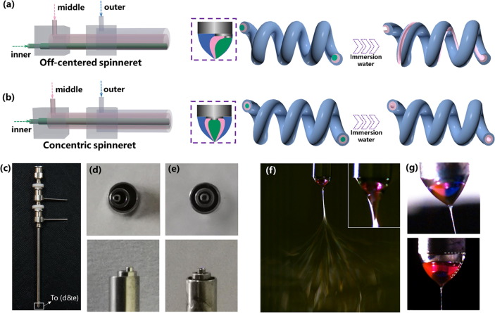
Grooves and other surface structures on the electrospun fibers are often seen as by-products or artefacts of the electrospinning process and are mainly controlled by the selection of solvents. However, in cases where it is the intention to create grooves on the electrospun fibers, modification of the electrospinning setup may be necessary to increase the predictability and consistency of getting grooves on the fibers. To do this, Zhao et al (2021) used a tri-fluid electrospinning technique where a tri-axial nozzle was used for the extrusion of different solutions. The three working components for their setup were cellulose acetate (CA), thermoplastic polyurethane (TPU), and polyvinylpyrrolidone (PVP). CA and TPU were the outer and middle components and PVP was the inner sacrificial component to be removed for the generation of hollow or groove structure. CA and TPU were selected due to their significant difference in modulus which encouraged the formation of helical nanofibers. For the formation of groove structure, the channels of the tri-axial spinneret were off-centered. With the core channel off-set to one side, the water soluble PVP core will be nearer to one side of the fiber. After the fibers were immersed in water, dissolution of the PVP formed a groove along one side of the fiber. To maintain a helical shape of the fiber, the flow rate of the PVP solution core needs to be sufficiently low as higher PVP solution flow rate results in mostly straight fibers. This is probably due to greater core thickness at higher core flow rate which resists bending of the electrospinning jet.
Published date: 13 August 2014
Last updated: 17 February 2026
▼ Reference
-
Amiraliyan N, Nouri M, Kish M H. Effects of Some Electrospinning Parameters on Morphology of Natural Silk-Based Nanofibers. J Appl Polym Sci 2009; 113: 226.
-
An H R, Ahn H J. Morphology control of Nb-doped SnO2 nanofibres formed via electrospinning: From hollow nanofibres to dense nanofibres. Journal of Ceramic Processing Research 2013; 14: 371.
Open Access
-
Celebioglu A, Uyar T. Electrospun porous cellulose acetate fibers from volatile solvent mixture. Materials Letters 2011; 65: 2291.
-
Chen S H, Chang Y, Lee K R, Lai J Y. A three-dimensional dual-layer nano/microfibrous structure of electrospun chitosan/poly(D,L-lactide) membrane for the improvement of cytocompatibility. Journal of Membrane Science 2014; 450: 224.
-
Demir M M. Investigation on glassy skin formation of porous polystyrene fibers electrospun from DMF. eXPRESS Polymer Letters 2010; 4: 2.
Open Access
-
Dhanalakshmi M, Jog J P. Preparation and characterization of electrospun fibers of Nylon 11. eXPRESS Polymer Letters 2008; 2: 540.
Open Access
-
Dong X, Wang J, Cui Q, Liu G, Yu W. Preparation of LaFeO3 Porous Hollow Nanofibers by Electrospinning. International Journal of Chemistry 2009; 1: 13.
-
Elishav O, Polia Lk, Naamat I, Beilin V, Shter G E, S. Grader G S. Lamellar-like Electrospun Mesoporous Ti-Al-O Nanofibers. Materials 201; 12(2): 252.
Open Access
-
Fashandi H, Karimi M. Pore formation in polystyrene fiber by superimposing temperature and relative humidity of electrospinning atmosphere. Polymer 2012; 53: 5832.
-
Goktas A. Electrospinning of polystyrene/butyl rubber blends: A parameteric study. MSc Thesis 2008. Middle East Technical University.
Open Access
-
Gopal R. Influence of Electrospun Nanofibrous Architecture in Separation Technology. PhD Thesis, National University of Singapore, 2010.
Open Access
-
Holzmeister A, Yarin A L, Wendorff J H. Barb formation in electrospinning: Experimental and theoretical investigations. Polymer 2010; 51: 2769.
-
Huang C, Niu H, Wu J, Ke Q, Mo X, Lin T. Needleless Electrospinning of Polystyrene Fibers with an Oriented Surface Line Texture. Journal of Nanomaterials 2012; 473872.
Open Access
-
Huang C, Tang Y, Liu X, Sutti A, Ke Q, Mo X, Wang X, Morsi Y, Lin T. Electrospinning of nanofibres with parallel line surface texture for improvement of nerve cell growth. Soft Matter 2011; 7: 10812.
-
Huang J, Zhang Y, Yu H, Han G, Cheng W. Cellulose-Based Triboelectric Nanogenerator Prepared by Multi-Fluid Electrospinning for Respiratory Protection and Self-Powered Sensing. Actuators. 2024; 13(5):178.
https://www.mdpi.com/2076-0825/13/5/178 Open Access.
-
Kim K, Kang M, Chin I J, Jin H J. Unique Surface Morphology of Electrospun Polystyrene Fibers from a N,N-Dimethylformamide Solution. Macromolecular Research 2005; 13: 533.
-
Koombhongse S, Liu W, Reneker D H. Flat Polymer Ribbons and Other Shapes by Electrospinning. Journal of Polymer Science Part B: Polymer Physics 2001; 39: 2598.
Open Access
-
Koski A, Yim K, Shivkumar S. Effect of molecular weight on fibrous PVA produced by electrospinning. Materials Letters 2004; 58: 493.
-
Li M M, Long Y Z, Yin H X, Zhang Z M. Electrospun cerium nitrate/polymer composite ?bres: synthesis, characterization and ?bre-division model. Chin. Phys. B 2011; 20: 048101.
-
Liu W J, Huang C, Jin X Y. Electrospinning of Grooved Polystyrene Fibers: Effect of Solvent Systems. Nanoscale Research Letters 2015; 10: 237.
Open Access
-
Wang X, Chen S, Chen X, Wu J, Huang Z, Wang J, Chen F, Liu C. Biomimetic multi-channel nerve conduits with micro/nanostructures for rapid nerve repair. Bioactive Materials 2024; 41: 577.
https://www.sciencedirect.com/science/article/pii/S2452199X24002895 Open Access
-
Xia X, Dong X J, Wei Q F, Cai Y B, Lu K Y. Formation mechanism of porous hollow SnO2 nanofibers prepared by one-step electrospinning. eXPRESS Polymer Letters 2012; 6: 169.
Open Access
-
Zaarour B, Lei Zhu L, Huang C, Jin X. Controlling the Secondary Surface Morphology of Electrospun PVDF Nanofibers by Regulating the Solvent and Relative Humidity. Nanoscale Research Letters 2018; 13: 285
Open Access
-
Zeng J, Kang Y H, Su G T. Formation of drug-loaded electrospun twin fibers. Chin. Sci. Bull. 2012; 57: 1275.
Open Access
-
Zhang D, Davoodi P, Li X, Liu Y, Wang W, Huang Y Y S. An empirical model to evaluate the effects of environmental humidity on the formation of wrinkled, creased and porous fibre morphology from electrospinning. Sci Rep 10, 18783 (2020).
Open Access
-
Zhao T, Zheng Y, Zhang X, Teng D, Xu Y, Yongchun Zeng Y. Design of helical groove/hollow nanofibers via tri-fluid electrospinning. Materials & Design 2021; 205: 109705.
Open Access
▲ Close list