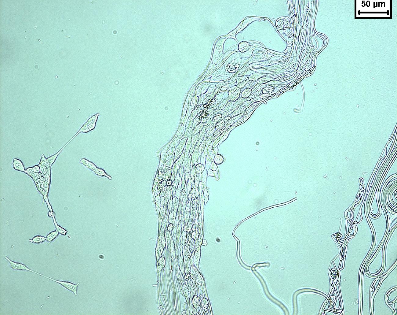
Since the early 2000s, electrospun products have been widely investigated for use in the biomedical application. Since natural extracellular matrix (ECM) is mainly made out of collagen nanofibers, it has been hypothesized that the similar dimensional constituents of electrospun scaffold will give it an advantage as implantable graft. From a clinical perspective, the highly porous matrix made of interconnected fibers allows nutrients and biomolecules to infiltrate or cross the scaffold to support the attached cells which is not possible using film. Multiple contact points on a nanofibrous substrate would also facilitate cell migration and adhesion as compared to a smooth surface (See figure 1).
Having a highly porous matrix with interconnected pores may not be sufficient as cells are able to sense their underlying substrate surface topography. Palo et al (2019) compared the response of fibroblast on solvent cast film, 3D printing on solvent cast film and cross-linked electrospun nanofibers (mean diameter of 230 nm) on solvent cast film. All the materials used for constructing the substrates were made of a blend of polyvinyl alcohol (PVA) and sodium alginate (SA). Tests on cell biocompatibility using fibroblasts also showed no significant difference in the cell viability between SC/3D printed dressing and SC film. However, with the electrospun layer, cell viability was greater. Cell adhesion and proliferation was significantly higher with cross-linked electrospun nanofibers on solvent cast film compared to solvent cast film and 3D printing on solvent cast film.
The fibrous porous scaffold produced by electrospinning has been compared with porous scaffold produced by lyophilization for Schwann cells (SCs) growth. Using chitosan as the model polymer in a comparative study, Wu et al (2021) showed that both structures were able to support growth of Schwann cells (SCs) . The pores on the electrospun membrane were much smaller than the scaffold produced by lyophilization. SCs on the electrospun membrane were spread out across the surface of the membrane as the small pore size prevented the SCs from penetrating into it. On a lyophilized scaffold, the SCs form clusters within each pore. Proliferation and adhesion was found to be higher on electrospun scaffold which may be due to greater similarity of fibrous electrospun scaffold to natural extracellular matrix (ECM) and better cell-cell communication. Greater amount of brain-derived neurotrophic factor was also secreted by SCs cultured on electrospun scaffold compared to lyophilized scaffold.
Till date, electrospun scaffold has been tested for potential use as nerve, bone, cartilage, liver, skin, heart and vascular graft. Electrospun fibers have also been used in other biomedical applications such as sensors or coating for stent and metal implants.
The microenvironment provided by electrospun scaffold has been shown to influence production of growth factors by cells cultured on it. Liu et al (2023) constructed a scaffold with electrospun polycaprolactone (PCL) nanofibrous yarns forming square grids as the base and electrospun gelatin over it. The PCL nanofibrous yarn contained Indocyanine green (ICG) which is a photothermal dye that is capable of converting the absorbed light energy into thermal energy and welding the fibers. Human adipose stem cells (hADSCs) were cultured on the electrospun scaffold for 24 h and the cell cultured medium was then extracted and tested for its influence on human skin fibroblasts (HSF) and human umbilical vein endothelial cells (HUVECs). hADSCs cultured on the scaffold with the smallest square grid (3 mm length) (SNSG) had the highest viability and proliferation. The conditioned medium from the SNSG group also showed the highest level of endothelial growth factor (EGF) and fibroblast growth factor-2 (FGF2). When the conditioned medium was added to HSF culture, the viability and the migration of HSF as shown on a scratch test was significantly better than the controls. Similarly, when the conditioned medium was added to HUVECs culture on matrigel, the HUVECs showed greater propensity for tube formation.
Electrospinning is also a highly versatile technique which enables researchers to modify the setup for their purpose. Yang et al (2022) used co-axial electrospinning to distribute cells throughout the scaffold and to maximize cell adhesion. Human bone mesenchymal stem cells (hBMSCs) used in their study was loaded onto the shell of their poly (3-hydroxybutyrate-co-4-hydroxybutyrate) (PHB) core and poly (vinyl alcohol) (PVA) shell fiber. PVA was used as the shell material as it is water soluble and the cell culture media containing hBMSCs was mixed with the PVA solution before electrospinning. Although the core material, PHB, was dissolved in CH2CL2, the solvent does not seem to have a significant impact on the viability of the cells. The cell survival rate at 3 days was found to be 97% which is the same as the control where cells are seeded onto electrospun PHB/PVA fibers. However, in the terms of cell adhesion, there was much greater hBMSCs adhesion with the cells embedded in the shell of the coaxial electrospinning compared to hBMSCs that was seeded after scaffold production. Since PVA is water soluble, it may gradually solubilize in an aqueous environment and freeing the cells to migrate or reconstruct the scaffold. Qavi et al (2023) envisioned the use of electrospinning to create capillary vessels with diameters ranging from 5 to 10 µm in particular, fenestrated capillaries with pores 80 to 100 nm in diameter. Coaxial electrospinning was used to create the hollow microtubes as capillary vessels. Polycaprolactone (PCL) dissolved in dichloromethane (DCM) was used as the sheath solution. Due to the high volatility of DCM, PCL goes through phase separation during electrospinning to form a porous wall. Polyethylene oxide (PEO) was used as the core material and it was later removed by soaking the fibers in DI water for an hour to form tubes.
Material non-specificity
A key advantage of electrospinning is the wide range of materials including additives that can be electrospun to form nanofibers. Polymers ranging from non-biodegradable to biodegradable have been electrospun (Read more) and investigated for use as implantable grafts. Biodegradable polymers that are used in clinical devices such as polylactide, polydioxanone, polyglycolic acid and polycaprolactone have already been electrospun [See Link]. In electrospinning of natural polymers in particular collagen, there are debates whether the electrospun protein is able to maintain its natural molecular structure. Matthews et al (2002) showed the presence of 67 nm banding pattern that characterizes native collagen. However, almost no subsequent studies repeated this observation until Iafisco et al (2012) once again showed the banding from electrospun collagen Type I (equine Achilles tendon) with acetic acid solution. Activated platelet rich plasma is known to contain concentrated amount of growth factors and cytokines which has been shown to be effective in accelerating healing in a number of tissues. Wolfe et al (2018) was able to use electrospinning to form nanofibers made of human platelet rich plasma (PRP) that has been lyophilized to form a powdered preparation rich in growth factors (PRGF). PRGF was dissolved in 1,1,1,3,3,3-hexafluoro-2-propanol (HFP) before electrospinning to produce fibers. The resultant electrospun scaffold exhibited a sustained release of important proteins for tissue regeneration for up to 35 days. Stability of the electrospun fibers may be due to the presence of fibrinogen and hemoglobin in the PRGF.
Beyond biocompatibility of the base material, drugs and other biomolecules have been incorporated into the electrospun fibers to take advantage of the synergy of chemical and physical cues used in combination. This flexibility is particularly useful in driving stem cell differentiation (Read more).
Biomolecules / Drugs
Ease of incorporating biomolecules into the nanofibers either through direct spinning, solution blending or post-spinning processing allows electrospun scaffold to use chemical cues to influence cell behavior. Protein used in this process does not denature through heat since high temperature is not required but the solvent used to form the solution may still have an effect. Nevertheless, there are methods such as core-shell electrospinningor emulsion electrospinning that reduces the contact between the protein and the organic solvent during electrospinning. Another method is to use post-spinning process to introduce proteins or other biomolecules onto the surface of the constructed nanofibrous scaffold.
Blending is probably the most commonly used method of introducing biomolecules to the electrospun scaffold. Collagen, growth factors, glycosaminoglycan and many other biomolecules have been blended with polymer solution and electrospun to form nanofibers scaffolds. The natural ECM contains a variety of proteins and biomolecules that act as biological cue to seeded cells. It may not be feasible to replicate .the composition of the biomolecules by selective addition of individual molecule in a man-made scaffold. However, Grant et al (2019) attempted to recreate this composition by solubilizing the decellularized ECM of the targeted organ and mixing with a polymer solution before electrospinning. In their study, they used a blend of decellularized liver extracellular matrix (hLECM) and poly-L-lactic acid (PLLA) solution and electrospinning. THLE-3 hepatocytes were cultured on hLECM/PLLA scaffold, polymer only scaffold and polymer scaffold containing individual ECM component (Collagen I, Laminin-521 and Fibronectin) for comparison. hLECM and all the individual proteins were solubilized prior to blending with PLLA solution. The presence of electrospun PLLA fibers increases the Young's Modulus of the decellularized ECM scaffold thereby providing mechanical support for hepatocytes. All electrospun scaffolds were able to maintain hepatocyte growth and albumin production. However, only hLECMcultured on hLECM/PLLA scaffold showed albumin expression increasing over time. On day 16, upregulation of cytochrome P450s (CYP1A1, CYP1A2 and CYP3A4), a family of enzymes involved in metabolism of drugs and other toxic compounds in the liver, were shown on hepatocytes cultured on hLECM/PLLA scaffold. Collagen IV was downregulated over time on all single protein scaffolds but increases for hLECM/PLLA scaffold. This study demonstrated the role of hLECM in introducing the complex biological cue to influence the response of hepatocytes and its synergy with electrospun scaffold in a lab-based environment.
Electrospun scaffold has been shown to encourage rapid cell adhesion. This rapid cell adhesion on electrospun fibers may in turn encourage early drug uptake by the cells. Chu et al (2023) tested the cellular uptake efficiency of released drugs by the nanofibers and nanoparticles using cultured mouse macrophages. At 0.5 h, the cell uptake from the nanofibers was 2.7 times higher than pure nanoparticles although there was no significant difference between the two at 4h. For celecoxib PLGA nanoparticles (Cel-NPs), the cumulative release of celecoxib was 44% within the first 3 hours. Subsequently, a cumulative release of 82% was recorded within 72 h. In contrast, electrospun PVA loaded with Cel-NPs (Cel-NPs-NFs) had a cumulative release of 68% at 168 h which is much slower than Cel-NPs. While drug-loaded nanoparticles showed rapid drug release, the lack of adhesion may delay the drug uptake process by the cells. In contrast, the faster adhesion of the cells on the nanofiber membrane may have allowed earlier absorption of the drugs.
Biomolecules may be attached to electrospun fibers after the scaffold has been formed by covalent bonding. Cross-linking technique has been used to bond peptides to electrospun fibers. Laboy-López et al (2022) covalently bonds adhesive peptides KRSR, RGD, and growth factor BMP-2 on the surface of electrospun porous cellulose acetate (CA) fiber mat. A deacetylation procedure followed by oxidation to form carboxylic terminals for further bioconjugation on the electrospun CA fiers. Carbodiimide crosslinking technique was used to attach the peptides to the activated CA fibers. Laboy-López et al (2022) were able to couple the peptides individually on the CA fibers and all three peptides on the CA fibers. Fetal osteoblasts, hFOB, were cultured on the bioactivated mat to investigate their response to the individual peptides and when the peptides were combined. A combination of peptides on the fibers were found to induce greater proliferation and increased integrin activation for short term culture of 1 to 7 days.
Biomimetic Structure
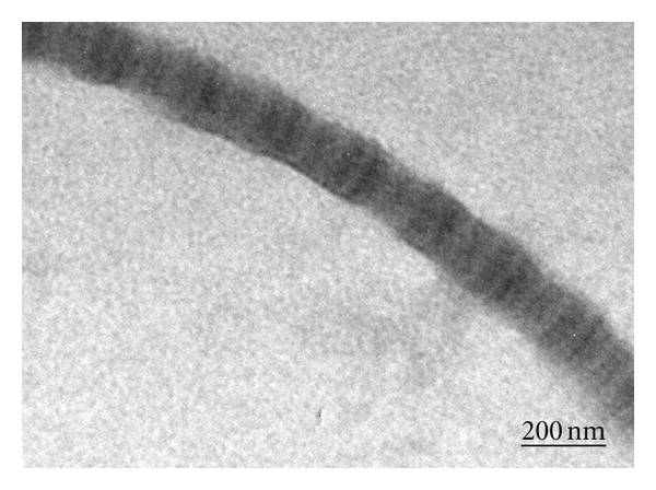
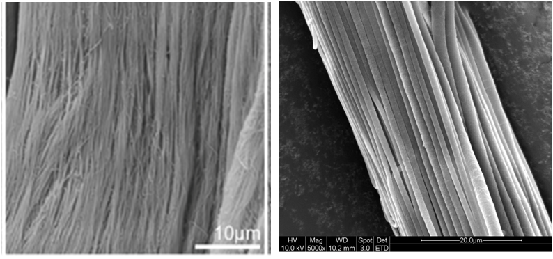
The nanofibers found in natural extracellular matrix (ECM) are often hierarchically organized from the nano-level up to the macro-level. The ability to exert some control on the electrospun nanofibers orientation and structure allow us to tailor the scaffold to match the intended replacement host tissue. Although current electrospinning technology is still unable to replicate the full complexity of the higher organized organs, researchers were able to construct electrospun scaffold that does resemble selected organ/tissue ECM organization (See figure 2).
The importance of surface topography in mimicking ECM has been demonstrated by Zavagna et al (2024). Zavagna et al (2024) used polycaprolactone (PCL) and polyacrylonitrile (PAN) for electrospinning into fibrous scaffolds to mimic the basement layer of intestinal epithelial barrier. Recombinant collagen type I, gelatin type B and fibrin (obtained with a quick crosslinking of fibrinogen and thrombin), were coated on the scaffold surface to improve cell adhesion. Human colon adenocarcinoma tumoral cells (Caco-2) were cultured on the coated scaffolds to determine its gene expression in particular, those in the formation and function of tight junctions and microvilli, such as, ZO-1, Occludin and Ezrin. Compared with Caco-2 cultured on Transwell, ZO-1 and Ezrin gene expression levels were similar in all the scaffold/coating conditions but only Ezrin was upregulated in Transwell. Occludin was only upregulated in PAN and PCL scaffolds coated with collagen. Hence the scaffold topography also plays an important role in influencing gene expressions.
At the macromolecular level, there have been attempts to mimic the physical forms of proteins which may enhance protein adsorption and cell interactions. Perez-Puyana et al (2021) demonstrated the feasibility of using poly(ε-caprolactone) (PCL) as the base polymer and natural proteins (gelatin, collagen, and elastin) as the template to create imprints on PCL. To create the imprinted PCL fiber, a solution of the protein and PCL was blended and electrospun into fibers. Solvent extraction was used to remove the protein from the blended fibers. With gelatin imprinted on PCL fibers, the resultant fibers showed good site specificity towards gelatin. The gelatin imprinted PCL fibers also showed better adsorption of collagen and elastin compared to non-imprinted PCL. Collagen-imprinted PCL fibers did not show any site specificity towards collagen, gelatin and elastin although general adsorption of these three proteins were better than non-imprinted PCL fibers. The non-specificity of collagen-imprinted PCL may be due to denaturation of collagen protein on the hydrophobic PCL fibers or the solvent. The harmful effect of solvents on collagen has been discussed in several references. Hence the collagen imprint may be structurally different from pristine collagen. Elastin-imprinted PCL fibers did not show any better protein adsorption compared to non-imprinted PCL. This has been attributed to interchain cross-linking of elastin which may have altered the protein structure and reduced protein rebinding on the fiber. For both collagen and gelatin-printed PCL fibers, the better protein adsorption may be advantages in cell culture. Storage duration of the fibrous scaffold may be improved with the absence of easily degradable proteins.
Benefits of high porosity - Greater protein adsorption
Apart from allowing nutrients and other biomolecules to be transferred into and through the scaffold, the high porosity and surface area of the electrospun fibrous mesh also allows greater amount of proteins to be adsorbed onto the scaffold. This may be a reason why cell adhesion on electrospun membrane is typically faster than other scaffolds. Comparing poly(D,L-lactide) (PLA) cast film, PLA solid nanofiber and PLLA porous nanofiber, solid fiber scaffolds adsorb 16x more proteins than solvent-cast and porous fiber scaffold adsorb 80% more proteins than solid nanofiber scaffold after 24 h [Leong et al 2009]. Solid nanofiber was found to have 15 x more surface area compared to solvent cast film of equivalent mass.
Rapid cell capture/adhesion
Electrospun nanofibrous membrane has been shown to encourage early cell attachment on its surface. This is very useful in clinical application where rapid cell capture on a scaffold is desirable. A study using osteoblast showed more than 30% cell attachment on the surface of poly-L-lactic acid nanofiber surface compared to about 10% on tissue culture plate (TCP) [Ngiam 2010] at 30 min. This property was also observed in the adhesion of hematopoietic stem cell (HSC) on collagen and PLGA/collagen blend where about 25% of HSC was captured on the nanofiber at 30 min as compared to only about 2% on TCP[Ma et al 2008]. Significantly higher percentage of MSC was also found to adhere on electrospun membrane at 1 hour (50 to 71%) compared to smooth film (28%) of the same material [Finne-Wistrand et al 2008]. From table 1, it is apparent that a fibrous surface encourages faster cell adhesion compared to smooth surface. Apart from surface roughness, fibers with biomolecules incorporated would further encourages cell adhesion on the substrate [Chan et al 2009].
Table 1. Comparison of cell adhesion/capture on different substrates.
| Reference
|
Cell type
|
Substrate
|
Duration
|
Percentage cell capture/adhesion
|
| Ngiam 2010
|
Osteoblast
|
Poly-L-lactic nanofiber
|
30 min
|
30%
|
| TCP
|
10%
|
| Ma et al 2008
|
Hematopoietic stem cell
|
PLGA/collagen blend (1:1),
|
30 min
|
23%
|
| TCP
|
2%
|
| PLGA
|
8%
|
| Collagen
|
26%
|
| Finne-Wistrand et al 2008
|
MSC
|
Electrospun poly[(L-lactide)-co-(1,5-dioxepan-2-one)]
|
60 min
|
50 to 71%
|
| Film poly[(L-lactide)-co-(1,5-dioxepan-2-one)]
|
28%
|
| Chan et al 2009
|
Human MSC
|
Tissue culture plastic bottom
|
30 min
|
3.2%
|
| Naked glass coverslip
|
3.3%
|
| Gelatin coated coverslip
|
5.3%
|
| Collagen-coated coverslip
|
3.6%
|
| P(LLA-CL) nanofiber, 480 nm
|
9.7%
|
| Air-plasma P(LLA-CL) nanofiber
|
27%
|
| Collagen-coated P(LLA-CL) nanofiber
|
40%
|
| Collagen microfiber, dia. 1140 nm
|
43%
|
| Collagen nanofiber, dia. 390 nm
|
45.1%
|
| CD49a antibody conjugated collagen nanofiber
|
50%
|
| CD29 antibody conjugated collagen nanofiber
|
55%
|
In a novel experiment, mineralized 3D nanofibrous scaffold with yarn microstructure was used to capture nucleated cells from bone marrow. After 20 min, 80% of the nucleated cells were captured on the mineralized 3D scaffold with 76% of the cells expressing MSC markers (CD44) [Ngiam 2010]. It is also possible to use thin nanofibrous membrane (thin-layer-3d-mem.html) or cut nanofibrous membrane (3dmembrane-frag.html) to capture the cells prior to meshing the membrane and cells to form a 3D nanofibrous scaffold where structural integrity is not required . Another way of forming 3D scaffold is to stack layers of fiber membrane (stack-layers.html) or rolling the membrane to form a concentric layered cylindrical rod.
Cell/tissue carrier
For autograft transplation, the transferred tissue may suffer from rapid degeneration and extracellular matrix (ECM) breakdown resulting in poor functional recovery. A tissue carrier provides an artificial scaffold for the cells to migrate onto when the initial ECM breaksdown prior to the regeneration of new ECM. An electrospun 3D nanofibrous scaffold has been demonstrated to be an effective carrier of fat fragments as a bioartificial graft. Cell viability was maintained throughout the scaffold up to 4 weeks in cell culture solution compared with bulk fat which suffers from rapid cell death at its core. Endothelial cells were also observed to be viable and possibly remained in its tubular arrangement at the end of the study in the bioartificial graft (4 weeks) [Panneerselvan et al 2013].
The dense fiber network of electrospun membrane presents a barrier for cell entry. Given its high porosity, this property makes electrospun membrane a good candidate for islet which is used as an immunoisolation strategy for disease treatment [Buitinga et al 2013]. Animal study has demonstrated the effectiveness of a electrospun pouch that prevents cell migration into the lumen without the formation of thick fibrous capsule [Krishna et al 2011].
Cells may also be carried within electrospun fibers by electrospinning solution containing living cells in it. Yeo et al (2023) prepared a cell-laden bioink containing alginate and polyethylene oxide (PEO) (A2P3) in water. Mesenchymal stem cells (MSCs) and smooth muscle cells (SMCs) were added to the A2P3 aqueous solution prior to electrospinning and 3D cell printing (CP). Cell viability after 7 days of culture was found to be more than 90% for both CP scaffold and electrospun scaffold. The cell-printed scaffold had a plain bulk structure and the cells had a round shape while cells in the electrospun scaffold showed elongation morphology along the length of the fiber. Cells on electrospun scaffold showed higher F-actin aspect ratios and orientation factor and the SMCs showed greater expressions of fibronectin, collagen I and collagen (IV). Therefore the ability of electrospinning to produce finer structure compared to cell printing was able to produce a scaffold more conducive for cell expression.
Biocompatible Barrier/Coating
Electrospinning and the resultant biocompatible membrane offers two significant benefits. Firstly, it is easy to use electrospinning for coating a layer of nanofibers on a surface. Secondly, the mesh consisting of fibers give it a certain level of structural integrity. Electrospun TiO2 has been shown to encourage cell differentiation and create an osteogenic environment [Wang et al 2012]. Thus electrospun TiO2 may be deposited on Ti implants to improve osseo-integration [Lim et al 2008]. The structural integrity of a nanofiber mesh has also been tested as a supporting layer for neural prosthesis. With a hydrogel as the main drug release agent, electrospun membrane was used to reduce the hydrogel disintegration and function as a barrier to resist implantation force [Han et al 2011].
Liu et al (2023) used electrospun membrane comprising of poly(lactic-co-glycolic acid)/poly(lactide)-b-poly(ethylene glycol) (PLGA/PLA-b-PEG) as anti-adhesion fibrous membrane for inguinal hernia repair. The use of conventional polypropylene (PP) mesh is known to result in an immune response close to the spermatic cord and spermatic vessels which led to the adhesion of the reticular and spermatic cords. In a rabbit model, PP mesh alone was found to induce inflammatory response at an early stage which resulted in significant and persistent adhesions, spermatic cord obstructions, and orchiatrophy. Electrospun PLGA/PLA-b-PEG membrane placed between the PP mesh and the spermatic cord on one side prevented contact between the spermatic cord and the PP mesh. The presence of the electrospun mesh as a physical barrier results in a significant reduction in inflammation. Interestingly, as the electrospun mesh fully degrades at day 180, minimal inflammatory response was observed with no evidence of adhesion. This may be due to peritonealization of PP mesh with fibrous tissue taking over the PP mesh as the electrospun mesh degrades hence forming a new physical barrier to protect the spermatic cord.
Contact Guidance
Several studies have shown that cells cultured on aligned electrospun fibrous substrate, exhibit contact guidance. This is particularly useful in neural engineering where the suitability of the scaffold is determined in part from the length neurite extension. In highly aligned nanofiber substrate, neurite outgrowth can be as much as 20% longer than that on random fibers [Corey et al 2007] although the presence of misaligned fiber has been shown to impede the extension [Wang et al 2009]. Schwann cells were also shown to elongate along the direction of fiber orientation [Corey et al 2007].
Guidance of the cell by the nanofibers may not be restricted to the top most layer. Investigation of neurite outgrowth by primary dorsal root gangelia have demonstrated neurite growth influenced by the orientation of the underyling nanofibers in a double-layered scaffold [Xie et al 2009]. Two aligned nanofibers membrane are fabricated and placed in such a way that the upper and lower membrane fiber orientation are orthogonal to one another. When the upper layer of nanofibers is sufficiently thin, neurite growth growing in contact alignment with the upper oriented nanofibers may occasionally turn perpendicular to match the underlaying fiber orientation.
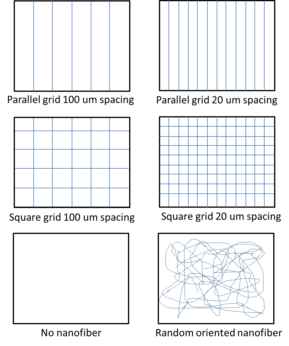
In a study by Fuh et al [2013], the behavior of embryonic kidney cells were tested on fiber (diameter about 700 nm) grids formed on a polypyrrole substrates as shown in figure 3. The study showed distinct cell alignment on the parallel grids with fiber-fiber spacing of 20 um demonstrating better cell orientation than 100 um spacing. No cell orientation was recorded for other substrates. Investigation of cell spreading showed that the spreading is the same for parallel grid and square grid of the same spacing. However, cell spreading is reduced when the spacing between the fibers are reduced for both square and parallel grids.
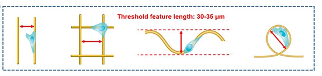
Zhang et al (2022) investigated the migration of human breast cancer adenocarcinoma cell (highest persistent 2D migration among all breast cancer cell lines) on polystyrene-coated glass slides with patterned microfibers (average diameter of 3 + 1 µm) using electrospinning. On parallel fiber tracks, the cells were able to bridge gaps of less than 30 µm between fibers. When the gap is more than 35 µm, the cells would stay on the same fiber. As the width of the cells are below 18 µm, gaps of more than 35 µm, is too great for them to reach across. On grids created by orthogonal overlaid fibers, cells would sometimes cross over to the orthogonal fiber. Consistent with the fibers laid in parallel, bridging between pores formed by the grid only occurred when the gap was less than 35 µm. On other fiber patterns such as wavy and loop, bridging and coverage by the cell is also dependent on whether the gap between segments of the fiber are more than 35 µm or less than 30 µm. The average step speed of the cells were between 0.2 and 0.5 µm min-1 on all four fiber patterns with no significant difference in their speed. It is important to note that the speed of the cell is measured based on the distance covered on the fiber and not a specific direction on the surface.
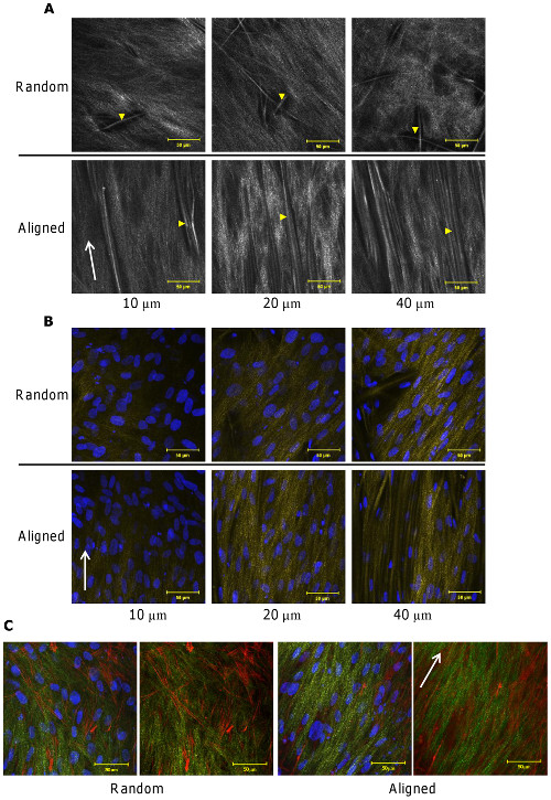
Apart from contact guidance of the cells on aligned fibers, the deposition of collagen fibers were also found to align with the orientation of the fibers. Using second harmonic generation (a minimally invasive, two photon based technique for visualization of collagen) to examine the the deposition of normal human dermal fibroblasts on electrospun polycaprolactone microfibers (about 8 um), collagen appeared to be more organized and oriented on aligned microfibers while collagen deposited on random microfibers did not show any preferential organization. Such collagen distributions were observed down to 100 um depth within the scaffolds [Delaine-Smith R M et al 2014].
In vivo study of implanted aligned fibrous scaffold in a subcutaneous rat model also showed that collagen fiber deposited was aligned whereas collagen fibers deposited on randomly oriented fibrous scaffold was not [Ifkovits et al 2010].
When combined with flowing medium, aligned fibers topography has been shown to significantly influence differentiation of stem cells. In the investigation of fibrochondrogenic differentiation of MSCs, Zhong et al (2013) cultured MSCs in a microfluidic platform with aligned nanofibers as the substrate for MSCs culture and subjecting the cells to flow direction from parallel to perpendicular with respect to the fiber orientation. Even with flow rate of 1 dyne/cm perpendicular to the fiber orientation, the MSCs were still oriented parallel to the fiber orientation although it has a more polygonal shape. Expression of fibrochondrogenic markers after 4 weeks were highest when the flow rate is perpendicular to the fiber orientation while cells cultured on static media exhibit the least expression.
Degradation characteristics
The high surface area and porosity of nanofibrous structure has been shown to exhibit degradation characteristic that differs from conventional solid structure. Polyglycolic acid (PGA) in nanofibrous form degrades faster than solid structures due to its high surface area. However, in PLGA and P(LLA-CL), the degradation is slower in nanofibrous structure compared to solid bulk.
Study of the degradation profile of PLGA and P(LLA-CL) nanofibrous structure showed a linear lost in the molecular weight over time without evidence of sharp reduction as seen in block form [Dong 2009]. The sharp drop in molecular weight of block form has been attributed to auto-catalytic degradation due to the accumulation of acidic by-products. In the nanofibrous form, the high porosity allows fast leaching or neutralization of the acidic by-products which prevents the onset of auto-catalytic degradation.
Published date: 06 October 2013
Last updated: 25 March 2025
▼ Reference
-
Buitinga M, Truckenmuller R, Engelse M A, Moroni L, Hoopen H W M T, van Blitterswijk C A, de Koning E J P, van Apeldoorn A A, Karperien M. Microwell Scaffolds for the Extrahepatic Transplantation of Islets of Langerhans. PLOS ONE 2013; 8: 64772.
Open Access
-
Chan C K, Liao S, Li B, Lareu R R, Larrick J W, Ramakrishna S, Raghunath M. Early adhesive behavior of bone-marrow-derived mesenchymal stem cells on collagen electrospun fibers. Biomed Mater 2009; 4: 035006.
-
Chu K, Zhu Y, Lu G, Huang S, Yang C, Zheng J, Chen J, Ban J, Jia H, Lu Z. Formation of Hydrophilic Nanofibers from Nanostructural Design in the Co-Encapsulation of Celecoxib through Electrospinning. Pharmaceutics. 2023; 15(3):730.
Open Access
-
Corey J M, Lin D Y, Mycek K B, Chen Q, Samuel S, Feldman E L, Martin D C. Aligned electrospun nano?bers specify the direction of dorsal root ganglia neurite growth. J Biomed Mater Res 2007; 83A: 636.
-
Delaine-Smith R M, Green N H, Matcher S J, MacNeil S, Reilly G C. Monitoring Fibrous Scaffold Guidance of Three-Dimensional Collagen Organisation Using Minimally-Invasive Second Harmonic Generation. PLoS ONE 2014; 9(2): e89761. doi:10.1371/journal.pone.0089761
Open Access
-
Dong Y X (2009) Nanofiber covered stent for vascular diseases. PhD Thesis, NUS.
Open Access
-
Finne-Wistrand A, Albertsson A C, Kwon O H, Kawazoe N, Chen G, Kang I K, Hasuda H, Gong J, Ito Y. Resorbable Scaffolds from Three Different Techniques: Electrospun Fabrics, Salt-Leaching Porous Films, and Smooth Flat Surfaces. Macromol. Biosci. 2008; 8: 951.
-
Fuh Y K, Chen S Z, He Z Y. Direct-write, highly aligned chitosan-poly(ethylene oxide) nanofiber patterns for cell morphology and spreading control. Nanoscale Research Letters 2013; 8: 97.
Open Access
-
Grant R, Hallett J, Forbes S, Hay D, Callanan A. Blended electrospinning with human liver extracellular matrix for engineering new hepatic microenvironments. Scientific Reports 2019; 9: 6293.
Open Access
-
Han N, Rao S S, Johnson J, Parikh K S, Bradley P A, Lannutti J J, Winter J O. Hydrogel-electrospun fiber mat composite coatings for neural prostheses. Frontiers in Neuroengineering 2011; 4: 1.
-
Iafisco M, Foltran I, Sabbatini S, Tosi G, Roveri N. Electrospun Nanostructured Fibers of Collagen-Biomimetic Apatite on Titanium Alloy. Bioinorganic Chemistry and Applications 2012; 2012: 123953.
Open Access
-
Ifkovits J L, Wu K, Mauck R L, Burdick J A. The Influence of Fibrous Elastomer Structure and Porosity on Matrix Organization. PLoS ONE 2010; 5(12): e15717. doi:10.1371/journal.pone.0015717.
Open Access
-
Krishna L, Clayton L R, Boland E D, Reed R M, Hoying J B, Williams S K. Cellular Immunoisolation for Islet Transplantation by a Novel Dual Porosity Electrospun Membrane. Transplant Proc. 2011 43: 3256.
Open Access
-
Laboy-López S, Fernández P O M, Padilla-Zayas J G, Nicolau E. Bioactive Cellulose Acetate Electrospun Mats as Scaffolds for Bone Tissue Regeneration. International Journal of Biomaterials 2022; 2022: 3255039
Open Access
-
Leong M F, Chian K S, Mhaisalkar P S, Ong W F, Ratner B D. Effect of electrospun poly(D,L-lactide) fibrous scaffold with nanoporous surface on attachment of porcine esophageal epithelial cells and protein adsorption. J Biomed Mater Res 2009; 89A: 1040
-
Lim J I, Yu B, Woo K M, Lee Y K. Immobilization of TiO2 nanofibers on titanium plates for implant applications. Applied Surface Science 2008; 255: 2456.
-
Liu N, Zhou Z, Ning X, Zhang X, Guo Q, Guo M, Wang Y, Wu T. Enhancing the paracrine effects of adipose stem cells using nanofiber-based meshes prepared by light-welding for accelerating wound healing. Materials & Design 2023; 225: 111582.
Open Access
-
Liu Z, Wang L, Ren Y, Chen H, Li S, Li S, Xu S, Liu Y. Protective effectiveness of electrospinning fibrous membrane in inguinal hernia repair. Materials & Design 2023; 231: 112074.
Open Access
-
Ma K, Chan C K, Liao S, Hwang W Y K, Feng Q, Ramakrishna S. Electrospun nanofiber scaffolds for rapid and rich capture of bone marrow-derived hematopoietic stem cells. Biomaterials 2008; 29: 2096.
-
Matthews J A, Wnek G E, Simpson D G, Bowlin G L. Electrospinning of collagen nanofibers. Biomacromolecules 2002; 3: 232.
-
Ngiam M L. Differentiation of bone marrow derived mesenchymal stem cells (BM-MSCs) using engineered nanofiber substrates. PhD thesis. National University of Singapore 2010.
Open Access
-
Palo M, Rönkönharju S, Tiirik K, Viidik L, Sandler N, Kogermann K. Bi-Layered Polymer Carriers with Surface Modification by Electrospinning for Potential Wound Care Applications. Pharmaceutics 2019; 11(12): 678.
Open Access
-
Panneerselvan A, Nguyen L T, Su Y, Teo W E, Liao S, Ramakrishna S, Chan C W. Cell viability and angiogenic potential of a bioartificial adipose substitute. J Tissue Eng Regen Med. 2013. Ahead of print.
-
Perez-Puyana V, Wieringa P, Guerrero A, Romero A, Lorenzo Moroni L. (Macro)Molecular Imprinting of Proteins on PCL Electrospun Scaffolds. ACS Appl. Mater. Interfaces 2021; 13: 29293
Open Access
-
Qavi I, Tan G. Process control of electrospinning artificial fenestrated capillary vessels. Materials & Design 2023 ; 227: 111708.
Open Access
-
Wang H B, Mullins M E, Cregg J M, Hurtado A, Oudgea M, Trombley M W, Gilbert R J. Creation of highly aligned electrospun poly-L-lactic acid ?bers for nerve regeneration applications. J. Neural Eng. 2009; 6: 016001.
-
Wang X, Gittens R A, Song R, Tannenbaum R, Olivares-Navarrete R, Schwartz Z, Chen H, Boyan B D. Effects of Structural Properties of Electrospun TiO2 Nano-fiber Meshes on their Osteogenic Potential. Acta Biomater. 2012; 8: 878.
Open Access
-
Wolfe P S, Sell S A, Ericksen J J, Simpson D G, Bowlin G L. The Creation of Electrospun Nanofibers from Platelet Rich Plasma. J Tissue Sci Eng 2011; 2: 107.
Open Access
-
Wu Y X, Ma H, Wang J L, Qu W. Production of chitosan scaffolds by lyophilization or electrospinning: which is better for peripheral nerve regeneration? Neural Regeneration Research 2021; 16: 1093.
Open Access
-
Xie J, MacEwan M R, Li X, Sakiyama-Elbert S E, Xia Y. Neurite Outgrowth on Nanofiber Scaffolds with Different Orders, Structures, and Surface Properties. ACS Nano 2009; 3: 1151.
-
Yang L, Zhao Y, Cui D, Liu Y, Zou Q, Xu S, Luo S, Ye C. Coaxial bioelectrospinning of P34HB/PVA microfibers biomimetic scaffolds with simultaneity cell-laden for improving bone regeneration. Materials & Design 2022; 213: 110349.
Open Access
-
Yeo M, Yoon J W, Park G T, Shin S C, Song Y C, Cheon Y I, Lee B J, Kim G H, Kim J H. Esophageal wound healing by aligned smooth muscle cell-laden nanofibrous patch. Materials Today Bio 2023; 19: 100564.
Open Access
-
Youngstrom D W, Barrett J G, Jose R R, Kaplan D L. Functional Characterization of Detergent-Decellularized Equine Tendon Extracellular Matrix for Tissue Engineering Applications. PLoS ONE 2013; 8(5): e64151. doi:10.1371/journal.pone.0064151.
Open Access
-
Zavagna L, Canelli E F, Azimi B, Troisi F, Scarpelli L, Macchi T, Gallone G, Labardi M, Giovannoni R, Milazzo M, Danti S. Electrospun Fiber-Based Tubular Structures as 3D Scaffolds to Generate In Vitro Models for Small Intestine. Macromolecular Materials and Engineering 2024; 10;: 2400123.
https://onlinelibrary.wiley.com/doi/full/10.1002/mame.202400123 Open Access
-
Zhang D, Sheng Y, Piano N, Jakuszeit T, Cozens E J, Dong L, Buell A K, Pollet A, Lei L M, Wang W, Terentjev E, Huang Y Y S. Cancer cell migration on straight, wavy, loop and grid microfibre patterns. 2022 Biofabrication 14 024102.
Open Access
-
Zhong W, Zhang W, Wang S, Qin J. Regulation of Fibrochondrogenesis of Mesenchymal Stem Cells in an Integrated Microfluidic Platform Embedded with Biomimetic Nanofibrous Scaffolds. PLoS ONE 2013; 8(4): e61283. doi:10.1371/journal.pone.0061283
Open Access
▲ Close list