Home | About | Contact


Electrospun Hybrid Tube Structure

Depending on the application requirement, electrospun fibrous tube made out of a single material may not be adequate. A hybrid structure may thus be necessary to meet the requirements. One of the simplest methods of creating a hybrid structure is by switching the materials to be electrospun on the template rod or by changing the electrospinning conditions that such different layered fiber organization can be realized. Zhu et al (2011) was able to construct a nerve conduit with longitudinally aligned electrospun fibers and randomly oriented electrospun fibers for the outer layer. For their setup, they first used two rods placed in-line with one another with a gap between such that it forms a parallel electrodes collector setup. This encourages the fibers to deposit across the gap to give longitudinally aligned fibers. After which a solid rod was passed through the lumen of the deposited fibers. Another round of electrospinning was subsequently carried out to deposit randomly oriented fibers over the longitudinally aligned fibers [Zhu et al 2011]. It is also possible to further increase the rod collector rotation speed or to use auxiliary electrodes to modify the electric field profile such that a further layer of circumferentially aligned fibers are deposited over the randomly oriented fibers.

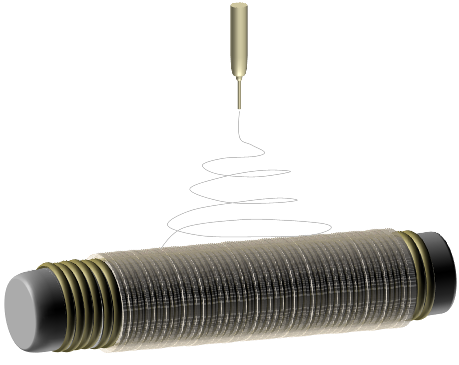
Electrospinning on microfiber rolled-on tube
Figure 1. Electrospinning on microfiber rolled-on tube

Moving beyond electrospinning, other processes have also been used in combination to form hybrid tubular structures. A common concern with electrospun tube is its ability to withstand pressure from within. To improve the mechanical properties, a simple method is to coat the electrospun fibrous tube with another layer of stronger polymer to form an outer film. Wang et al (2014) first electrospun circumferentially aligned poly(L-lactide) fibers on a rod. Next, the electrospun scaffold on the rod was rolled over a polydimethylsiloxane (PDMS) solution surface to avoid penetration of PDMS into the fibrous scaffold before heat curing the coated layer of PDMS. The completed structure was then finally taken off the rod to obtain a composite tube. Sato et al (2010) created a hybrid tube with electrospun fibers at the lumen and an outer layer of fibroin sponge. This was constructed by placing the electrospun fibers while still on the rod, in a cylindrical mold. A fibroin/poly(ethylene glycol) diglycidyl ether solution was then poured into the mold at the spacing between the electrospun fibers and the wall of the mold. A freeze-thawing process was subsequently carried out and the poly(ethylene glycol) diglycidyl ether removed by washing with distilled water to form the fibroin sponge. An alternative method of constructing nanofiber/freeze dried hybrid tube is to lay the nanofiber sheet on the freeze-dried substrate and rolling. Mottaghitalab et al (2013) first constructed aligned silk fibroin/fibronectin fibers using a rotating drum collector. The aligned nanofiber sheet was laid on a freeze-dried silk/single wall carbon nanotube before rolling up with the aligned nanofiber sheet in the lumen. This is a simple method of assembling longitudinally aligned nanofibers in the lumen of the hybrid tube. However, a disadvantage is that the rolled up tube has the risk of unraveling if it is not secured properly.


Scanning electron micrographs of: a) porous structure of freeze-dried conduits, b) Aligned fibronectin nanofibers produced through electrospining process. [Mottaghitalab et al. PLoS ONE 2013; 8(9): e74417. doi:10.1371/journal.pone.0074417. This work is licensed under a Creative Commons Attribution 4.0 International.]

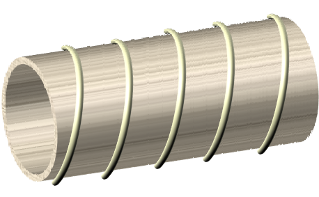
An alternative method is to use microfiber as reinforcement to form a hybrid structure. Microfibers reinforcement has been used both at the lumen and on the external of the hybrid tube. For the construction of microfibers/nanofibers hybrid with the microfibers in the lumen, the microfibers are first deposited on a rod template. Microfibers fabrication methods include gravity spinning [Williamson et al 2006] or melt extrusion spinning [Chung et al 2010]. Electrospinning is then used to coat a layer of nanofiber over the microfibers. Even without the use of a bonding agent, the bonding between the electrospun nanofibers and the underlying microfibers is adequate to prevent separation [Chung et al 2010]. This may be due to the compressive force exerting on the microfibers as the electrospun nanofibers were wound onto the mandrel with the microfibers. To imitate the structure of trachea, Hung et al (2014) used 3 mm and 1.5 mm diameter flexible PLLA wire to coil around metal rod with 1.5 cm diameter and 0.5 cm diameter respectively with regular spacing between each coil. A thin layer of dichloromethane was applied on the PLLA wire coil to facilitate adhesion between electrospun fibers coated over the PLLA coil. The resultant hybrid tube is physically similar to native trachea and demonstrated good resistance to radial compression that exceeds that of native trachea. For construction of a hybrid tube with microfibers wound externally over electrospun fibers, Centola et al (2010) used fused deposition to wind a coil of polycaprolactone on the outer surface of an electrospun tube. Apart from using microfibers as mechanical reinforcement, other coating or overlaying methods have also been used.

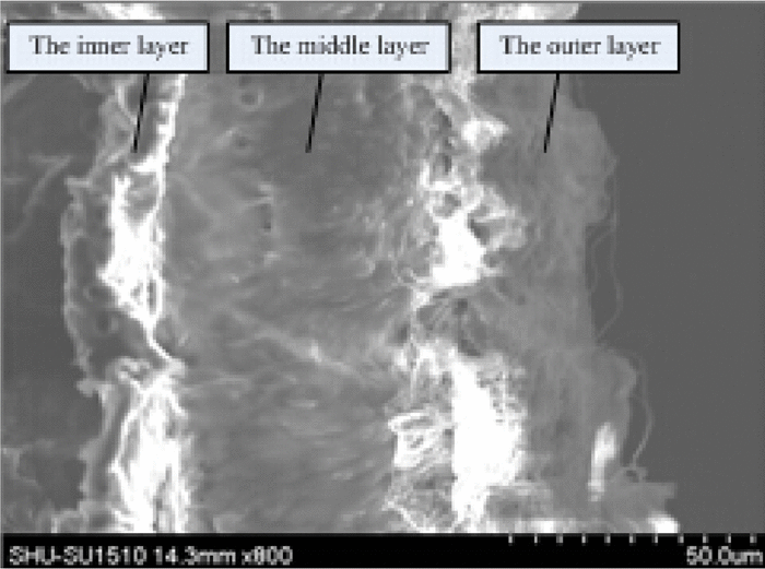
For some applications such as vascular grafts, the mechanical strength of electrospun tubes may not be adequate. To overcome this limitation of electrospun tubes, Liu et al (2015) constructed a tri-layer tube with a micro-imprinted poly-p-dioxanone (PPDO) middle layer sandwiched between electrospun chitosan/polyvinyl alcohol layers. The PPDO layer provides the mechanical support while the electrospun layers provide a favourable environment for cell proliferation. Comparison of the mechanical properties showed significantly better tensile strength and radial strength at 19.8 MPa and 128 KPa respectively for the tri-layer tube with comparable specimen thickness to electrospun only tube.


SEM micrograph of cross-section of three-layered composite graft. [Liu et al AIP Advances 5, 041318 (2015); http://dx.doi.org/10.1063/1.4906571. CC by 3.0 Unported License.]
Electrospun tube with microfiber reinforcement on the exterior
Figure 2. Electrospun tube with microfiber reinforcement on the exterior

In a reversal of role, electrospun fibers have been used to strengthen a weaker tube component. Jeong et al (2006) constructed a porous jellyfish collagen tubular scaffold using freeze-drying method. To reinforce the jellyfish collagen tubular scaffold, a layer of electrospun poly(lactide-co-glycolide) fibers was coated over the porous tube and the resultant hybrid tube showed an improvement in mechanical properties.

Hybrid tubes have also been created for the purpose of introducing different topography to the tube. To create longitudinal micropatterning on the lumen of a hybrid tube, Uttayarat et al (2010) first constructed a microgroove template using poly(dimethylsiloxane). This microgroove template is subsequently rolled onto a rod and secured using nail polish. Polyurethane solution was spun cast onto the slowly rotating rod with the template under a high-intensity halogen lamp. This accelerated drying of the polyurethane solution on the template. Electrospinning of polyurethane solution was carried out immediately after the spin casting process. Semi-dried spin casted polyurethane may favor good adhesion with the electrospun polyurethane fibers.


Published date: 16 July 2014
Last updated: 28 June 2016

Comments
[+]


Google Ad.