In most reported electrospinning where a collector plate is used, the resultant structure is a flat nanofibrous membrane. This is expected as the nanofibers just keep coating the collector plate. However, given the right conditions, a three-dimensional structure may be collected on a flat plate. Generally, a build-up of nanofibers is due to the influence of surface charges on the jet and the surrounding charges.
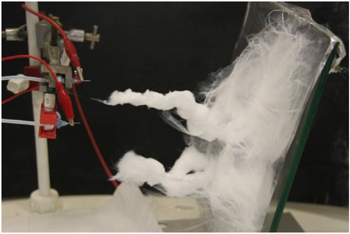
Figure 1. Induced charges at the tip of the collected fibers
In a series of experiment by Sun et al (2012), it was found that in situ formation of 3D structure is due to induction and polarization of electrostatic charges resulting in the gathering of opposing charge on the apex of the collected nanofibers which attracts incoming jet or fibers. This is verified by bringing a charged rod close to the apex of the deposited fibers. With the electrospinning charged by a positive voltage, the apex was shown to be attracted to a positively charged rod but repelled by a negatively charged rod. This shows that the tip of the deposited fibers were negatively charged. This results in preferential deposition of fibers on the fiber layer instead of the collector thereby encourages a rapid build-up of a tall nanofibrous structure. On an insulated collector, such a build-up of nanofibers were not observed as there was no electrical induction and a 2D membrane was formed instead. Removal of charges on the deposited fibers was also found to result in flat membrane [Sun et al 2012]. Although the tip of the deposited fibers may be negatively charged, the rest of the nanofibrous construct may be positively charged. Test by Tsai et al (2003) using a capacitive probe showed that electrospun membrane retained the same charge polarity as the voltage used to charge the solution. Tests using thermally simulated current experiment also showed that the residual charges on the electrospun membrane is of the same polarity as the voltage applied [Catalani et al 2007]. Since experimental results have shown that the residual charges on the deposited fiber is of the same polarity as the voltage applied and the demonstration by Sun et al (2012) that the apex of the 3D nanofibrous structure is of opposite polarity as the voltage applied, we can imagine that the induced negative charges were only found at the tip of the structure while most part of the structure were positively charged (assume positive voltage applied). With this distribution of charges, it explains why fibers continuously deposited at the apex of the structure and not on the other parts of the membrane. In a study by Vong et al (2018), the induction of the deposited fibers to a polarity opposite that of the nozzle seemed to be almost instantaneous. And such induction is continuous as the electrospinning proceeds. This was demonstrated with a charged rod between the nozzle tip and the collector, with the nozzle moving in a circular path, equi-distance to the collector. With the nozzle at a positive high voltage, the deposited fibers were attracted to a positively charged rod. With a negatively charged rod, the fibers standing from the collector were repelled. By using a de-ionizer to neutralize the charges on the deposited fibers, a flat membrane with significantly higher packing density is formed instead [Yousefzadeh et al 2012].
Cai (2013) was able to fabricate both fluffy nanofibrous scaffold and flat nanofibrous membrane of zein and polyethylene glycol by altering the surface resistivity of the fiber using additives. Fibers with lower surface resistivity (through the addition of sodium dodecyl sulfate) was able to form fluffy fibrous scaffold while those with higher resistivity form flat membrane. This supported his hypothesis that retained charges on fibers (due to higher resistivity) are more strongly attracted to the collector thus compacting them against the collector surface. On the contrary, fibers with lower resistivity will quickly lose its surface charges and allow incoming fibers to settle without much compaction. Charge induction may also occur as proposed by Sun et al (2012) and this may lead to repulsion of the fiber off the collector surface.
Self-bundling of cellulose acetate nanofibers from solution of 17.5% cellulose acetate, 1% lithium chloride and 1:1 DMAc: acetone solvent solution [Boyd et al. J. Cellulose Nanofibre Mesh for Use in Dental Materials. Coatings 2012; 2: 120. CC By 4.0].
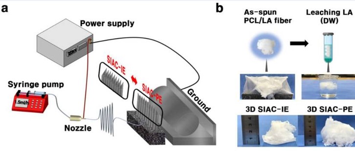
This seems to be in agreement with observations from other studies where materials/mixtures with higher conductivity has a greater tendency to form in-situ 3D structure. Materials that have been observed to form standing structures include polysulfone, polyacrylonitrile with carbon nanotubes [Yousefzadeh et al 2012; Heikkila and Harlin 2009] and polymers with addition of salt [Sun et al 2012]. In a study by Paneva et al (2010), it was demonstrated that high conductivity of the solution alone may not result in the development of standing fibrous structures. It was the addition of inorganic salt that induces self-organization of the deposited fibers toward the nozzle tip. However, a subsequent study by Vong et al (2018) suggested that having sufficiently high solution conductivity is able to encourage 3D scaffold formation. Vong et al (2018) compared the addition of ethanol and phosphoric acid 85% in water (H3PO4) to polystyrene (PS) solution to observe the effect on 3D scaffold formation. With ethanol dopent, only 2D membrane was formed. However, with H3PO4 dopent, a 3D structure started to form in seconds. This has been attributed to higher conductivity of the solution due to the addition of H3PO4. In an experiment by Cho et al (2019), they found that the addition of lactic acid (LA) into polycarpolactone (PCL) solution is necessary for the electrospun 3D PCL scaffold formation on their arryed collector. They hypothesized the carboxylic acid functional groups in LA, being negatively charged, contributed to electrostatic repulsion under the electric field and hence led to the formation of 3D cotton fiber scaffold. Without LA, electrospun PCL only forms a 2D membrane on the collector. Post electrospinning leaching of LA was carried out in water to further increase the porosity of the resultant scaffold. The relative humidity of the electrospinning environment was also found to influence the ability to form 3D scaffold even with the addition of LA. At relative humidity of less than 20%, only 2D membrane was formed. At humidity above 30%, traces of 3D structure starts to form on the collector. It is only at humidity above 40%, greater volume of 3D scaffold is formed.
(a) Schematic illustration of electrospinning set up. (b) LA leaching process of PCL/LA fibers [Cho et al 2019] .
Chinnakorn et al (2024) successfully used H3PO4 in the electrospinning of 3D polycaprolactone (PCL) by increasing the conductivity of the solution.
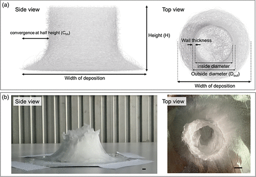
At the initial phase of electrospinning, the fibers spread over an area of the collector for a few seconds. Thereafter, the depositing fibers started to build up to form a 3D structure. However, due to the random whipping motion of the electrospinning jet, it is not possible to control the precision of the fiber deposition. It was found that as the structure built up, the diameter of the fibers started to increase. This has been attributed to the reducing distance between the nozzle tip and the deposition point at the top of the structure. In the absence of H3PO4 in the solution, only a flat PCL membrane was formed.
(a) Diagrams and (b) examples of parameters used to illustrate 3D electrospun structures in this work. The scale bar is 10 mm [Chinnakorn et al 2024].
Given numerous studies that support the hypothesis that solution with lower resistivity generally gives rise to in situ formation of 3D standing structure, inorganic precursor solution with its high concentration of ionic salt and greater conductance may see a higher incidence of 3D standing structure formation. Poologasundarampillai et al (2014) reported the fabrication of fluffy, cotton-wool-like bioactive glasses from electrospinning of silica precursor tetraethylorthosilicate and calcium nitrate tetrahydrate (Ca(NO3)2).4H2O. Distribution of Ca2+ and SiO4- ions were found to be inhomogeneous along the length of the fiber which demonstrates the influence of the electric field on the ions and possibly the formation of 3D fluffy structure. However, in the same report, electrospun SiO2 precursor solutions did not form 3D fluffy structure.
Unalan et al (2024) electrospun the precursors of various bioglass (SiO2-CaO) 3D scaffolds doped with zinc and copper ions by varying the composition of Ca, Zn and Cu. For some compositions such as 80Si-20Ca and 80Si-15Ca-5Cu, only 2D membranes were formed. With higher ratios of Cu or Zn to Ca such as 10% Ca and 80Si-10Zn-10Cu, the electrospinning was able to produce 3D scaffold in situ. This is contrary to the results from Poologasundarampillai et al (2014), 3D scaffolds from electrospinning of bioglass precursors were possible in the presence of calcium nitrate tetrahydrate but not in its absence. This is despite Unalan et al (2024) also using calcium nitrate tetrahydrate as part of the precursors. 3D formation from electrospinning has been attributed to higher charge density which are present in Ca, Zn, and Cu ions. Unalan et al (2024) suggested that other factors such as greater binding between the silicon dioxide (SiO2) and the zinc and copper ions that facilitate the formation of covalent bonds may have improved the structural integrity and mechanical strength hence contributing to the formation of 3D cotton-wool-like structure.
Given that there are very few reports of in situ formation of 3D standing structure from inorganic precursor solution and there must be other yet unknown factors for its formation which warrants further investigation.
In a more detailed study of electrospinning ionic salt precursors by Dong et al (2023), they found that spiking of the precursor solution to increase the conductivity of the solution may be needed to encourage the formation of in situ electrospun 3D structures. Using ethanol-based, titanium isopropoxide (TiP) and tetraethoxysilane (TEOS) solution with polyvinylpyrrolidone (PVP) and acetic acid (AcOH) for electrospinning, only 2D membranes were produced. By adding yttrium nitrate (Y(NO3)3·6H2O) to the solution, the electrospun jet forms a 3D structure. The addition of Y(NO3)3·6H2O increases the charge density and viscosity of the solution. The electrospinning jet bending was also closer to the nozzle tip due to greater work instability. Electrospinning jet was observed to deposit fibers that were standing perpendicular to the collector. This is due to charge polarization as described by Sun et al (2012). However, unlike the result by Sun et al (2012), 3D structures were still formed when the metal collector was replaced by an insulated collector.
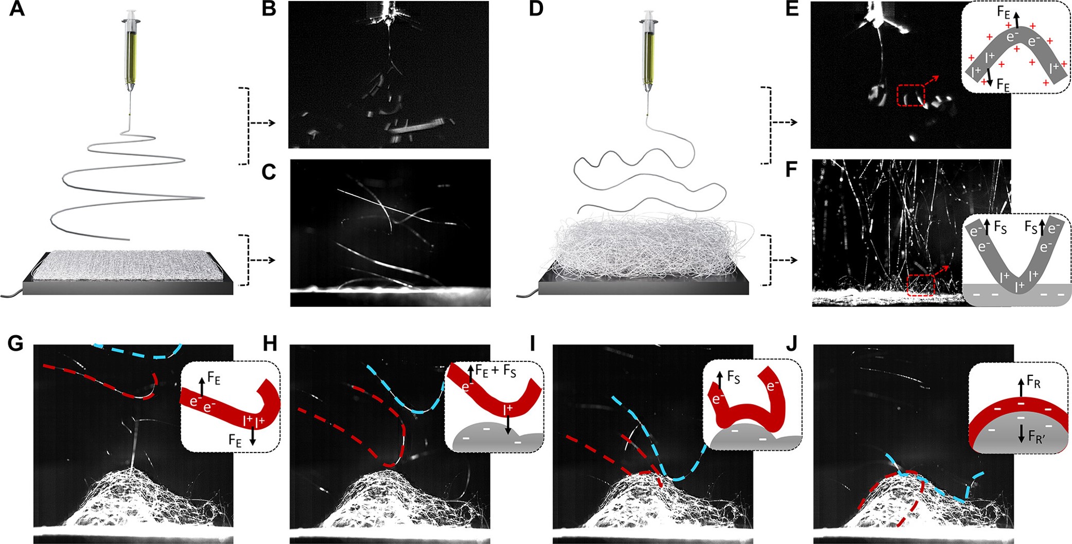
In situ observation of solution jet behavior and fiber assembling process. (A,D) Schematic illustrations of the 2D and 3D electrospinning processes, respectively. High-speed camera images taken near the nozzle (B,E) and at the substrate region (C,F) show the different behaviors of solution jets and solidified fibers. Inset in (E) schematically explains the formation of vertical spirals of the solution jet. The jet segment carries unevenly distributed charges. + represents the excessive charge from the high voltage. I+ (or e-) refers to positive (or negative) ions which redistribute inside the partially solidified fiber in response to the electric field. Such ions are subjected to an electrostatic force (FE) along (or opposite) the direction of electric field. Inset in (F) suggests that the top of the fiber assemblies is polarized by induced negative surface charges (white ?), thus exerting repulsive force (FS) on the negative ions inside fiber to reorientate the fiber upon landing. (G-J) In situ observation of fiber assembling process on the substrate. Two individual fibers are traced and labeled in red and blue, respectively. Schematics highlight the forces acting on red fiber, i.e., the electrostatic forces from the electric field (FE), the polarized fiber surface (FS), and the Columbic repulsions (FR), among nearby fibers once the fiber lands and undergoes polarization [Dong et al 2023]..
In another study by Shah et al (2012), varying the ratio of colloidal silica solution to polyethylene oxide (PEO) solution determines whether the electrospinning process yield 2D membrane or 3D scaffold. At ratio of 80:20 PEO/silica, electrospinning of the solution gave 2D nanofibres membrane. However, when the ratio of silica is increased to 50:50 to that of PEO, 3D nanofibres network was produced. Shah et al (2012) attributed the change of fibrous structure from 2D to 3D to the reduction in water content with a higher silica loading. As the experiment did not include checking of the solution conductivity, it is unknown whether this may have contributed to the formation of 3D structure.
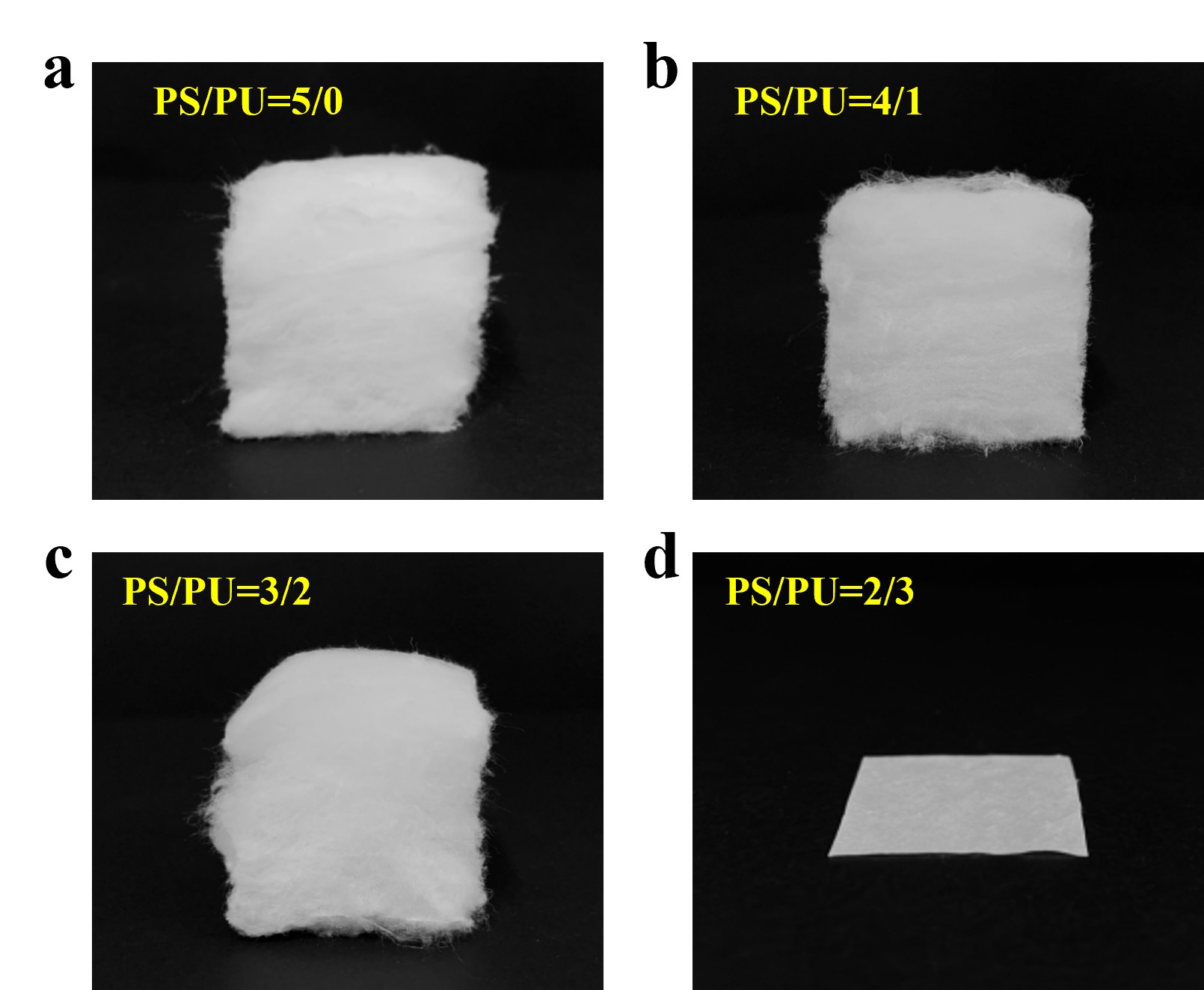
A less common hypothesis for the formation of 3D structure from electrospinning fibers is high stiffness of the material. With colloidal silica solution and polyethylene oxide (PEO) mixture, a higher silica ratio would increase the stiffness of the composite fibers. Wu et al (2025) electrospun a blend of polystyrene (PS) and polyurethane (PU) with the former being rigid and the latter as the softer component. They found that electrospun fibers with pure PS or PS to PU ratio with higher PS percentage formed a 3D sponge structure. When the ratio of PS to PU dropped to 2:3, flat 2D mesh was formed instead. Coulombic repulsion between electrospun fibers and the rigidity of PS may have prevented the fibers from collapsing into a 2D mesh. However, higher PS content may also cause higher conductivity or encourage charge retention both of which will favor 3D structure formation.
The optical photos of the PS/PU fibrous sponge with various PS/PU mass ratios of (a) 5/0, (b) 4/1, (c) 3/2, and (d) 2/3 [Wu et al 2025].
While most studies showed that a more conducting solution favors in situ formation of electrospun 3D structure, this is more often demonstrated when salt are added to a polymer solution. A polymer solution without any additives that shows greater conductivity does not necessarily have a greater likelihood to form 3D structure compared to another lower conductivity polymer solution. Bazrafshan et al (2018) ompared the electrospinning characteristic of collagen-g-poly(MMA-co-EA) (CME) and nylon 6 (N6). Measurement of the solutions conductivity showed that nylon 6 (N6) has a significantly higher conductivity than CME. However, during electrospinning, depositing CME fibers climbed towards the nozzle thus forming a 3D structure. In contrast, N6 just formed a flat 2D membrane. Beyond solution conductivity, there are probably other solution properties that determine whether electrospinning will form 3D structure in situ.
Humidity has also been shown to play a part in the formation of fluffy, cotton fibrous structure. Using polystyrene, Yoon et al (2017) showed at low humidity of 10%, electrospinning give rise to flat membrane. As the humidity was risen to 40%, the electrospinning jet starts to form fluffy, cotton structure. However, electrospinning polyamide at the same humidity of 40% did not give rise to fluffy structure. Such difference in fiber arrangement may be due to the solution properties and its interaction with the humidity of the environment given that the solutions comprised of different solvents. Unfortunately, this study did not check on the conductivity difference between the solutions and it would also be difficult to determine the changes in conductivity of the solution in the electrospinning jet as it travel through the environment.
Voltage applied to the electrospinning nozzle has also been found to affect the effectiveness of 3D scaffold formation. Vong et al (2018) demonstrated this effect with the electrospinning of polystyrene (PS) with phosphoric acid 85% in water (H3PO4) added to the solution. Formation of 3D scaffold was faster when a higher voltage is used. Given that induction of the deposited fiber is the main mechanism for 3D scaffold formation, a higher voltage at the nozzle would also accelerate charge induction on the deposited fibers. This in turn encourages 3D fiber formation.
Bonino et al [2012] suggested a different mechanism for the generation of 3D nanofibrous fluffy alginate/polyethylene structure. In their hypothesis, the initial layer of deposited nanofibers acts as an insulation which prevents the charges on subsequent nanofibers to discharge to earth and the uneven distribution of charges created an electric field that cause the building up of peaks. Although the paper mentioned that "subsequent layers of fibers are preferentially deposited in the vicinity of the peaks", it is unclear why this would cause the continual build-up of peaks instead of a more even distribution of the fibers.
The characteristics of the surface charges may be influenced by the humidity which favor the formation of the 3D structure [Bonino et a 2012]. Other factors that seem to increase the likelihood of 3D structure formation are high voltage, larger nozzle diameter and short nozzle to collector distance [Heikkila and Harlin 2009]. Deliberate modification of the setup to encourage rapid build up of nanofibers in the vertical direction may also achieve 3D structure. One concept is to use auxiliary electrodes to focus the electrospinning jet. A simple method is to have a disk attached to the spinneret tip. Electrospun 3D fibrous structures have demonstrated to show cell behavior that is more favorable than electrospun flat membrane although there are few such studies probably due to the difficulty in constructing 3D fibrous structures. Given that many tissues are essentially 3D, the ability to form 3D fluffy fibrous structures easily may lead to more clinically relevant investigation and utilization.
Bazrafshan Z, Stylios G K. One-Step Fabrication of Three-Dimensional Fibrous Collagen-Based Macrostructure with High Water Uptake Capability by Coaxial Electrospinning. Nanomaterials 2018; 8(10): 803.
Open Access
Bonino C A, Elfimenko K, Jeong S I, Krebs M D, Alsberg E, Khan S A. (2012) Three-Dimensional Electrospun Alginate Nanofiber Mats via Tailored Charge Repulsions. Small 8 pp. 1928.
Cai S. Electrospun Plant Protein Scaffolds with Fibers Oriented Randomly and Evenly in Three-Dimensions for Soft Tissue Engineering Applications. University of Nebraska. 2013. Master of Science Thesis.
Open Access
Catalani L H, Collins G, Jaffe M. Evidence for Molecular Orientation and Residual Charge in the Electrospinning of Poly(butylene terephthalate) Nanofibers. Macromolecules 2007; 40: 1693.
Chinnakorn A, Soi-Ngoen Y, Weeranantanapan O, Pakawanit P, Maensiri S, Srisom K, Janphuang P, Radacsi N, Nuansing W. Fabrication of 3D Polycaprolactone Macrostructures by 3D Electrospinning. ACS Biomater. Sci. Eng. 2024; 10: 5336.
https://pubs.acs.org/doi/full/10.1021/acsbiomaterials.4c00302 Open Access
Cho S H, Kim J I, Kim C S, Park C H, Kim I G. Harnessing the Topography of 3D Spongy-Like Electrospun Bundled Fibrous Scaffold via a Sharply Inclined Array Collector. Polymers 2019; 11: 1444. https://www.ncbi.nlm.nih.gov/pmc/articles/PMC6780350/
Open Access
Dong S, Maciejewska B M, Lißner M, Thomson D, Townsend D, Millar R, Petrinic N, Grobert N. Unveiling the Mechanism of the in Situ Formation of 3D Fiber Macroassemblies with Controlled Properties. ACS Nano 2023; 17: 6800.
Open Access
Heikkila P, Harlin A (2009) Electrospinning of polyacrylonitrile (PAN) solution: Effect of conductive additive and filler on the process. eXPRESS Polymer Letters 3, pp. 437-445.
Open Access
Paneva D, Manolova N, Rashkov I, Penchev H, Mihai M, Dragan E S. Self-Organization of Fibers into Yarns during Electrospinning of Polycation/polyanion polyelectrolyte pairs. Digest Journal of Nanomaterials and Biostructures 2010; 5: 811.
Open Access
Poologasundarampillai G, Wang D, Li S, Nakamura J, Bradley R, Lee P D, Stevens M M, McPhail D S, Kasuga T, Jones J R. Cotton-wool-like bioactive glasses for bone regeneration. Acta Biomaterialia 2014; 10: 3733.
Shah H V, Sandy J R, Ireland A J, Su B. Electrospinning of 2D and 3D silica nanofibres from a colloidal solution. Ceramics - Silikaty 2012; 56: 112.
Sun B, Long Y Z, Yu F, Li M M, Zhang H D, Li W J, Xu T X (2012) Self-assembly of a three-dimensional fibrous polymer sponge by electrospinning. Nanoscale 4 pp. 2134.
Tsai P, Schreuder-Gibson H L. The Role of Fiber Charging on Co-electrospinning and the Resident Life of the Residual Charges from the Electrospinning Process. Presented at the American Filtration and Separations Society Spring 2003 Meeting.
Unalan I, Rimoli I H, Mutlu N, Michálek M, Abraham G A, Liverani L, Boccaccini A R. Cotton wool-like ion-doped bioactive glass nanofibers: investigation of Zn and Cu combined effect. Biomed. Mater. 2024; 19: 065001.
https://iopscience.iop.org/article/10.1088/1748-605X/ad7084 Open Access
Vong M, E. Klomkliang S C, I. Akinwumia, Nuansing A W, Radacsi N. Controlled three-dimensional polystyrene micro- and nano-structures fabricated by three-dimensional electrospinning. RSC Adv. 2018; 8: 15501.
Open Access
Wu H, S.Wang, Zhang W. Surmenev R A, Y Jianyong, Shichao Zhang S, Ding B. Ultralight, Washable, and Antibacterial Ultrafine Fiber Sponges by Direct Electrospinning for High-Performance Warmth Retention. Macromol. Mater. 2025; e00101.
https://onlinelibrary.wiley.com/doi/full/10.1002/mame.202500101 Open Access
Yoon J W, Park Y, Kim J, Park C H. Multi-jet electrospinning of polystyrene/polyamide 6 blend: thermal and mechanical properties. Fash Text 2017; 4: 9.
Yousefzadeh M., Latifi M., Amani-Tehran M., Teo W. E., and Ramakrishna S. (2012) A Note on the 3D Structural Design of Electrospun Nanofibers, Journal of Engineered Fibers and Fabrics. vol 7 pg. 17-23
Open Access▲ Close list
Affiliation:
Institut de Chimie et Proc´ed´es pour l'Energie, l'Environnement et la Sant´e, ICPEES-UMR7515, Universit´e de Strasbourg, CNRS, Institut Carnot MICA, Ecole Europ´eenne de Chimie, Polym`eres et Mat´eriaux, 25 rue Becquerel, 67087 Strasbourg Cedex 2, France.
Karlsruhe Institute of Technology (KIT), Department of Chemistry and Bioscience, Institute of Chemical Technology and Polymer Chemistry, Engesserstrasse 18, 76131 Karlsruhe, Germany
Contribution: Providing Figure 2
Date: 2 April 2013
▲ Close Credit and Acknowledgement