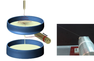
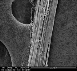
In a typical electrospinning setup, the nanofibers are deposited on a solid substrate and the resultant nanofibrous structure will be difficult to modify. However, to remodel the nanofibrous structure after deposition, a dynamic system which does not cause nanofiber breakage will be desirable. With this in mind, a fluid such as water has been identified as a possible substrate for nanofiber collection such that it can be manipulated after deposition in a continuous process.
Key advantages of using water as a working substrate,
- Nanofibers can potentially be oriented by movement on the water surface
- Adhesion between the nanofibers and the water surface is sufficiently weak such that the fiber integrity can be maintained when it is being transported by the water.
Using a dynamic fluid system, continuous nanofibrous yarn can be fabricated. A fiber deposition basin containing water needs to be sufficiently large surface area to capture the nanofibers. A water inlet and an outlet is required to keep the water flowing throughout fiber deposition.
In the most basic of setup, the moving water is only used to transport the deposited fibers away from the collection point. Water from the collecting basin continuously flows over an edge and it is recirculated back to the collection basin. As the water flows over the edge, the deposited fibers are also brought to the edge of the basin where it is lifted off the water surface and onto a collection spool [Liu et al 2013]. Upon lifting of the fiber mesh off the water, the surface tension of the water will cause the mesh to collapse into a bundle.
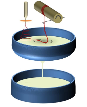
Instead of water flowing over the edge of the fiber deposition basin, a hole may be made at the base of that basin such that a vortex can be created by the draining water. The draining water would consolidate and pull the deposited nanofibers to form a yarn. Continuous nanofibrous yarn can be collected using this setup with speed up to 90 m/min. An important note for using this setup is that the rate of fiber deposition on the reservoir surface must be high enough such that the consolidated nanofibrous yarn has sufficient strength to withstand the drawing process.
|
Polymer
|
Solvent
|
Take-up speed
|
Reference
|
|
poly(vinylidene fluoride-cohexafluoropropylene)
|
40% dimethylacetamide and 60% acetone
|
1.05 m/s
|
Teo et al 2007
|
Pros
- Stable process
- Highly aligned fibers
- Consolidated fibers
Cons
- Require drying of the yarn
- Additional care required due to presence of water
Twisted Nanofibrous yarn
Since nanofiber has the tendency to "stick" on the surface of the water, this property has been used to create a flow profile to enable twisting of nanofibrous yarn. To create a twist, one point of the fiber must be rotated relative to another point along the principal axis of the fiber. As nanofibers are relatively weak, water with its high surface tension is able to provide sufficient holding force to twist the fiber relative to a fixed point without breaking the yarn. To create a twisting effect, the water must be circulating about the point where the yarn is going to be drawn. The circulating water can be created using a vortex flowing down a central hole in the basin.
As the fibers are deposited at one corner of the basin, the flowing water down the vortex would draw the fibers toward it. The circulation of the water is greatest at the edge of the vortex and this is where the yarn would be drawn off the surface of the water. As the yarn is guided through a stationary guide, the circulating water below would provide the necessary twisting force on the yarn.
Published date: 24 September 2012
Last updated: 05 January 2016
▼ Reference
-
Liu J, Liu Q, Ma S, Liang J, Ma X, Fong H. Continuous bundles of aligned electrospun polyacrylonitrile copolymer nanofibers prepared via the flowing water bath and their morphological, structural, and componential variations during the opposite-directional diffusion process. Polymer 2013; 54: 4987.
-
Wee-Eong Teo, Renuga Gopal, Ramakrishnan Ramaseshan Kazutoshi Fujihara, Seeram Ramakrishna (2007) A dynamic liquid support system for continuous electrospun yarn fabrication. Polymer vol. 48 pg. 3400-3405.
-
Yousefzadeh M., Latifi M., Amani-Tehran M., Teo W. E., and Ramakrishna S. (2012) A Note on the 3D Structural Design of Electrospun Nanofibers, Journal of Engineered Fibers and Fabrics. vol 7 pg. 17-23
▲ Close list
 ElectrospinTech


