Mass production of aligned electrospun fibers
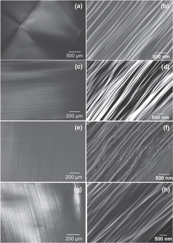 Examples of aligned nanofibers generated from a 1-emitter source (a), (b) and zigzag arrays with 1.5 mm emitter gap and 3 (c), (d), 7 (e), (f), and 17 (g), (h) emitters while flowing 1 ml h?1 per emitter. [Garcia-Lopez et al 2017]. |
Electrospinning are been used at an industrial level to produce nanofibers. However, most of the output are restricted to random organized nanofibers. Producing highly aligned electrospun nanofibers is challenging due to interference between multiple electrospinning jets. With a moving collector, it may be possible to overcome the interference between the electrospinning jets to get aligned fibers. Garcia-Lopez et al (2017) designed and constructed an electrospinning emitter array and reservoir using 3D printing and the solution used was polyethylene oxide (PEO) in water. The optimum emitters configuration comprised of 17 emitters with 1.5 mm emitter gap arranged in a zigzag manner. Each emitter is 4 mm tall and has a tapered spout with exit diameter of 300 µm. To reduce the generation of air cushion or turbulence on the surface of the rotating drum collector, a horizontal polyethylene plate was placed at drum height. With distance between emitter tip and a rotating drum collector at 8 cm with drum tangential rotation speed at 13.8 m/s, highly aligned PEO fibers were collected.
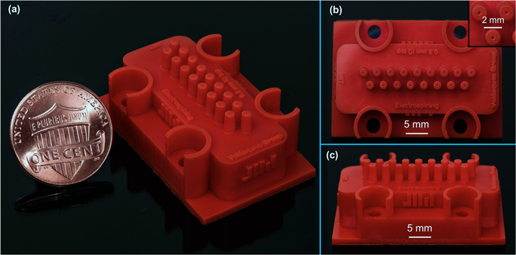 (a) Optical image of a 3D printed device with 17 emitters in zigzag near a one-cent US coin as comparison; (b) top-view of the device showing the zigzag packing of the emitters and close-up view of a cluster of emitters; (c) lateral view of the device evidencing the conical shape of the nozzles [Garcia-Lopez et al 2017]. |
Advances in near field electrospinning make it a potential way for mass production of nanofibers if it is possible to use multiple spinnerets. Wang et al (2015) investigated the parameters for multiple nozzles near field electrospinning. The parameters investigated include electrode-to-collector distance ranging from 2 to 6 mm and nozzle spacing between 2.1 to 3.5 mm. From mass production of conventional electrospinning, it is known that the electric field interference between the electrospinning jets will have an impact on the process. Similarly, when there are multiple nozzles, the distance between the deposition points are larger than the distance between the nozzles. With more nozzles, the deposition distance increases. In their setup, two to six nozzles are placed in two rows. Further research is needed to determine the impact of the fiber deposition when more nozzles in other configurations are used. The accuracy and precision of the fiber deposition from each nozzle will also need to be investigated when used as a group.
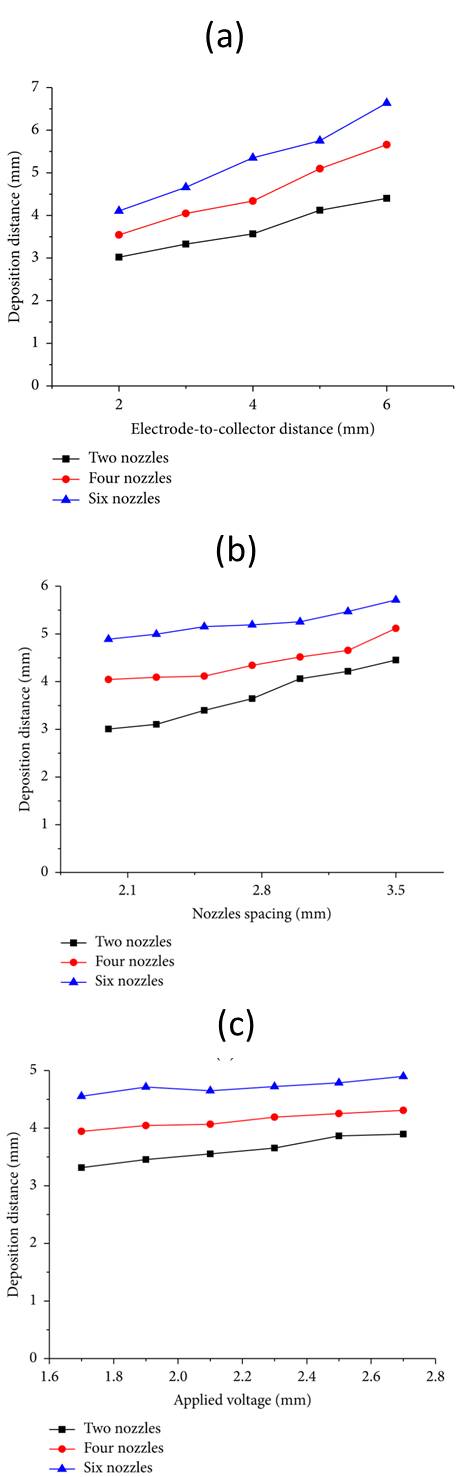 (a) Deposition distribution changes with different electrode-to-collector distance. (b) Deposition distribution changes with different nozzle spacing. (c) Deposition distribution changes with different applied voltage. [Wang et al 2015. This work is licensed under a Creative Commons Attribution 3.0 Unported License.] |
Using dual nozzles setup, Wang et al (2017) did a detailed study on the parameters influencing the deposition gap between them. Parameters such as needle length, needle spacing, applied voltage and electrode to collector distance were examined. The top three dominant parameters were found to be needle spacing, electrode to collector distance and needle length. It is easy to understand the influence of needle spacing and electrode to collector distance on the gap between deposited fibers. As electrospinning jets tend to repel one another, increasing the distance between the electrode and collector allows greater divergence upon deposition. With increasing needle length, the gap between deposited fibers increases. This has been attributed to its influence on the electric field profile. With a longer needle, the vertical component of the electric field gets reduced as the charges were spread over a longer length of the needle.
In a standard multi-nozzle setup, the high voltage is applied to the nozzles and this adds to the electric field interference within the electrospinning field. One way to reduce the charges on the nozzles is to apply the high voltage to the collector instead. Moon et al (2021) hypothesized that when a positive high voltage is applied on the collector, there is a migration of cations towards the induced negative polarity needle wall. However, as the movement of cation is slow, the presence of both cation and electrons in the electrospinning jet reduces the net interfacial charge on it. The reduced Coulombic repulsive forces on the electrospinning that causes bending instability is less than the stabilizing inertia and viscoelastic force hence there is greater jet stability. The diameter of the fibers were about 10 µm which is large for electrospun fibers. Such larger diameter also helped in the damping of the electrospinning jet.
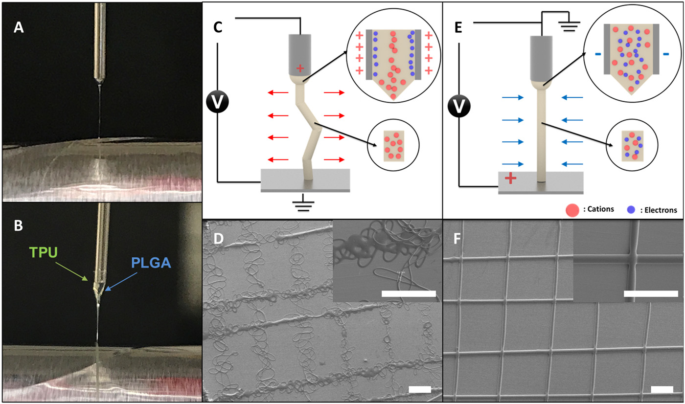 Mechanism of a straight jet. Digital images of Taylor cones for (A) a single-phasic microfiber and (B) a biphasic microfiber. PLGA was used for the single-phasic microfiber; PLGA and TPU were used for the biphasic microfiber. Schematic diagrams of the forces applied to the polymeric jet for (C) the conventional jetting system and (E) the CREW system. SEM images of grid patterns that are produced by (D) the conventional jetting system and (F) the CREW system. Scale bars, 300 µm. (Moon et al 2021) |
This setup for maintaining jet stability has been tested on several polymer solutions such as TPU, PLGA, polycaprolactone (PCL) and others across multiple nozzles simultaneously at inter-nozzle distance as low as 5 mm. Each electrospinning jet was able to maintain a stable trajectory and stacked to form parallel walls.
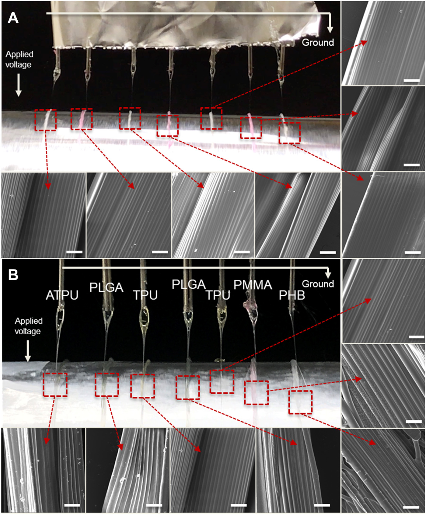 Digital images of the Taylor cones of seven polymer jets and SEM images of obtained microfiber bundles using seven needles in parallel (A) with TPU in the THF/DMF mixture with red and green dyes and (B) with various polymer materials such as the ATPU, PLGA, TPU, and PMMA in the THF/DMF mixture, and PHB in the chloroform/DMF mixture. Scale bars, 100 µm [Moon et al 2021]. |
Centrifugal electrospinning may be a potential method for mass production of aligned electrospun fibers. This concept uses a combination of centrifugal force and electrostatic force to stretch the solution droplets into jets. Without the application of high voltage, pure centrifugal spinning of fibers require the spinneret to rotate at thousands of rpm. However, in centrifugal electrospinning, the rotation speed can be reduced to 300 to 600 rpm [Liu et al 2013]. With the introduction of centrifugal force, a lower voltage is required to overcome the surface tension of the solution to initiate electrospinning. The combination of mechanical rotation and the reduced voltage makes this a very effective method for fabricating aligned nanofibers [Liu et al 2013]. Highly aligned polystyrene nanofibers have been constructed using an applied voltage of 3 kV with a low rotation speed of 420 rpm [Liu et al 2013] using dual spinnerets.
  Fig 1. (top) Centrifugal electrospinning setup schematic. (bottom) Aligned polystyrene nanofibers constructed from centrifugal electrospinning with applied voltage of 3 kV, rotation at 420 rpm and distance between tip and collector of 2.5 cm [Liu S L et al. Journal of Nanomaterials, vol. 2013, Article ID 713275, 9 pages, doi:10.1155/2013/713275. This work is licensed under a Creative Commons Attribution 3.0 Unported License.] |
Last updated: 13 December 2022
Reference
- Garcia-Lopez E, Olvera-Trejo D, Velasquez-Garcia L F. 3D printed multiplexed electrospinning sources for large-scale production of aligned nanofiber mats with small diameter spread. Nanotechnology 2017; 28: 425302. Open Access
- Liu S L, Long Y Z, Zhang Z H, Zhang H D, Sun B, Zhang J C, Han W P. Assembly of Oriented Ultrafine Polymer Fibers by Centrifugal Electrospinning. Journal of Nanomaterials 2013; 713275. Open Access
- Moon S, Jones M S, Seo E, Lee J, Lahann L, Jordahl J H, Lee K J, Lahann J. 3D jet writing of mechanically actuated tandem scaffolds. Science Advances 2021; 7 Open Access
- Wang Z, Chen X, Zeng J, Liang F, Wu P. Controllable deposition distance of aligned pattern via dual-nozzle near-field electrospinning. AIP Advances 2017; 7: 035310. Open Access
