Near field electrospinning is one of the leading techniques in accurate placement of nanofibers. This technique has evolved from using AFM tips to supply a limited volume of solution for electrospinning to nozzle-based system where a continuous stream of solution can be extruded. The precision and accuracy of the fiber deposition has also vastly improved from simple formation of oriented fibers on a collector to precise deposition of the fiber at a specific point. Despite the progress, several intrinsic limitation or characteristic of near-field electrospinning still needs to be noted when employing this technique.
Spinneret
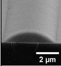
To spin nanofibers at such close distance, the initial radius of the jet needs to be small since stretching of the solution will be limited. By using an atomic force microscope tip with a small drop of solution at the tip, a small initial spinning radius can be achieved [Kameoka et al 2003]. This method, known as near-field electrospinning, has been shown to be capable of spinning nanofiber over trenches and also to create nanofiber patterns [Sun et al 2006]. However, having a tip with a drop of solution limits the length of fibers that can be produced before having to go for a refill. Using a spinneret with a reservoir of solution generally produces fibers with diameter of a few micrometers [Gupta et al 2007; Xue et al 2014] as there is a limit to which the capillary size can be reduced while allowing the solution to flow through it. The fibers may also be wet at deposition thus giving the fibers a semi-circular cross-section [Xue et al 2014]. Nevertheless, this did not stop researchers from using extremely fine needle to spin nanofibers [Chang et al 2008, Camillo et al 2013]. Chang et al (2008) used a 100 µm diameter needle tip to electrospin polyethylene oxide while Camillo et al (2013) a µm-diameter tip Tungsten spinneret in a 26 gauge needle to electrospin conjugated polymer, poly[2-methoxy-5-(2-ethylhexyloxy)-1,4-phenylenevinylene] (MEH-PPV) blended with polyethylene oxide. King et al (2019) showed in their near field electrospinning of polydioxanone solution, when the needle diameter reduces, there is a significant reduction in the resultant fiber diameter. An 18 Gauge needle (0.838 mm inner diameter) gave a fiber diameter of about 25 µm and a 23 Gauge needle (0.337 mm inner diameter) gave a fiber diameter of 6 µm.
Low voltage
Further development in the near field electrospinning spinning process have attempted to improve fiber deposition precision and reducing fiber diameter. Camillo et al (2013) was able to fabricate 100 nm diameter fiber at an applied voltage of 1.5 kV and a tip to collector distance of 500 µm using a modified fine tip spinneret. Separate reports by Chang et al (2008) and Bisht et al (2011) have shown that higher voltage leads to a significant increase in the fiber diameter (in the micrometer range) and loss of jet stability. The remedy is to significantly reduce the voltage used in the electrospinning process to about 200 to 600 V with tip to collector distance at about 0.5 to 1 mm. However, the charges on the solution drop at the tip of the needle were insufficient to break free from the surface tension to initiate electrospinning without assistance. Chang et al (2008) used a tungsten probe tip and Bisht et al (2011) used a glass microprobe tip (1 to 3 µm tip diameter) to mechanically draw the solution at the tip of the needle to initiate electrospinning. In the study by Chang et al (2008), reduction of electrospinning voltage from 1.5 kV (at tip to collector distance of 500 µm) to 600 V reduces the fiber diameter from 3 µm to 50 nm. Using a lower voltage of 200 V with tip to collector distance of 1 mm, Bisht et al (2011) was able to pattern nanofibers (polyethylene oxide) with diameter below 20 nm. Similar to electrospinning with longer tip to collector distance, it is likely that there is an optimum voltage which the fiber diameter obtained will be at its finest. Voltage higher or lower than this value will see an increase in the fiber diameter. Song et al (2015) showed that when the voltage for electrospinning polystyrene was increased from 400 to 500V, at a tip to collector distance of 20 µm, the fiber diameter reduced from close to 160 nm to about 60 nm. Such fiber diameter response to voltage is due to a balance of stretching of the jet and the speed at which it hit the collector. While increasing voltage causes greater stretching which reduces the fiber diameter, this also causes greater jet acceleration where the stretching terminates when the jet hit the collector.
To use a low working voltage in near field electrospinning while eliminating the need to use a physical object to initiate electrospinning, an alternative is to use a higher voltage for initiation of electrospinning and switch to a lower voltage once the jet has erupted from the nozzle. Huang et al (2014) used this concept with a movable stage collector to produce ordered patterns with interfiber pitch of 50 µm. By controlling the height between the nozzle tip and the collector stage and the speed of stage, fibers with different orientation and cross-sectional shape can be obtained. Generally, closer distance between nozzle tip and collector (ranging from 0.5 mm to 2 mm) results in flat fibers due to impaction of the electrospinning jet.
To maintain a high precision of fiber deposition for low voltage near field electrospinning, a smaller distance between collector and nozzle tip is recommended. In the experiments by George et al (2020) using polyacrylonitrile (PAN) solution, when the distance increases to 20 mm, coiled wires are formed instead. As the distance increases, the electrospinning jet has a longer "runway" to pick up speed. When the velocity of the electrospinning jet exceeds that of the collector movement, the wire will start to buckle and form coils on the collector.
King et al (2019) described the concept of initiating the electrospinning process with a higher voltage followed by reduction to the desired voltage. Using polydioxanone solution, an initial voltage of -1.8 kV was applied for tip to collector distance of less than 2 mm and -2.0 kV for distances greater or equal to 2 mm for 10 s. The voltage was then reduced to -1.1 kV as the working voltage. A limitation of the setup is that the landing point at electrospinning jet initiation cannot be determined although subsequent adjustment can be made after the jet has landed or the structure can be built up based on the displacement relative to the landing point. To control the landing point of the electrospinning jet, a target point may be set.
George et al (2020) used patterned carbon pillars with diameter of about 20 µm and spacing of less than 40µm on a silicon substrate to direct the deposition of electrospun fibers. The electrospun fibers were found to preferentially deposit on the edge of the pillars and an array of fibers were suspended across all the pillars with predetermined spacing. The pillars were also found to be able to guide the fiber to deposit on it even if the electrospinning jet was slightly offset by a small angle.
Low voltage, near field electrospinning has shown characteristics that differ from conventional near field electrospinning using higher voltage. Fiber diameter has already been shown to be smaller using this technique. With low voltage, near field electrospinning, the fiber diameter was found to be sensitive to the collector stage movement due to mechanical stretching; low velocity giving rise to larger fiber diameter and vice versa [Bisht et al 2011]. King et al (2019) also showed that as the velocity of the translational collector stage increases, the fiber diameter reduces. The electrospun polydioxanone fibers diameter collected at stage velocity of 10 mm/s and 100 mm/s were 10 µm and 3.7 µm respectively. Instead of very fine spinneret tip, Bisht et al (2011) showed that it is possible to spin fibers with diameter less than 100 nm using a 27 gauge needle (approx. 200 µm inner diameter).
Table: Precision of fiber deposition using Near Field Electrospinning
| Description |
Pitch between fibers |
Fiber diameter |
Material |
Reference |
| Near-Field electrospinning |
250 µm |
15 - 50 µm |
Polyhedral oligomeric silsesquioxane-poly(carbonate-urea)urethane, Polyhedral oligomeric silsesquioxane-polycaprolactone-poly(carbonate-urea)urethane |
Gupta et al 2007 |
| Near-Field electrospinning |
100 µm |
1 µm |
Polyvinylidene fluoride |
Chang et al 2012 |
| Near-field electrospinning, distance 0.5 cm |
50 µm |
150 nm |
Polyethylene oxide |
Chang et al 2008 |
| Near-field electrospinning, distance 0.5 cm, speed 20 cm/s |
20 µm |
700 nm |
Chitosan / Polyethylene oxide |
Fuh et al 2013 |
| Near-field electrospinning, distance 0.5 mm, speed 5 cm/s |
10 µm |
1 µm |
Polyethylene oxide |
Hellmann et al 2009 |
| Near-field electrospinning, distance 20 µm, speed 2 mm/s |
~5 µm |
~75nm |
Polystyrene |
Song et al 2015 |
| Near-field electrospinning, distance 0.5 mm, speed 50 cm/s |
100 µm |
100 nm |
Poly[2-methoxy-5-(2-ethylhexyloxy)-1,4-phenylenevinylene]/Polyethylene oxide |
Camillo et al 2013 |
| Near-Field electrospinning distance. 1.8 mm. |
Stacking |
10 µm |
polydioxanone |
King et al (2019) |
Electric field
Electrospinning jet can be very sensitive to variation in electric field. Thus a target with electric field profile that attracts the jet may be used to guide the electrospinning jet towards the desired landing point. Bisht et al (2011) demonstrated the precision and accuracy of low voltage, near field electrospinning by suspending fiber across carbon post with diameter of 30 µm and interpostal distance of 100 µm. Min et al (2013) used near field electrospinning to deposit semiconducting poly(3-hexylthiophene) (P3HT):PEO-blend organic nanowire over multiple field-effect transistors on a flexible polyarylate substrate at a speed of 13.3 cm/s with regular spacing of 50 µm and fiber diameter of 289 nm. They have also demonstrated the ability to spin highly aligned nanowires from other materials such as poly(9-vinyl carbazole) (PVK) and poly{[N,N'-bis(2-octyldodecyl)-naphthalene-1,4,5,8-bis(dicarboximide)-2,6-diyl]-alt-5,5'-(2,2'-bithiophene)}.
The combination of near-field electrospinning and a guiding electrode has the potential to obtain precise and accurate fiber deposition (Read Stable jet and guiding electrode combination, stable-guided-jet.html). Xu et al (2014) used a guiding electrode behind the collector to create a direct line from the nozzle tip to it. This significantly dampens the deviation of the electrospinning jet from its original path as a result of electrostatic repulsion from the preceding deposited nanofiber. Without the guiding electrode, the near-field electrospun fibers have a spread of 74 µm. With the guiding electrode, the spread was reduced to just 7 µm. This raises the possibility of building up 3D structures using electrospinning.
Having a conductive wire as the collection target is perhaps the most direct method of encouraging precise electrospun fiber deposition. Calzado-Delgado et al (2022) placed a copper wire (diameter 90 µm) on insulating paper to fabricate a wall of stacked electrospun fibers. The electrospinning nozzle moves horizontally at a high speed of 300 mm/s and vertically by 10 µm every 20 s. With these electrospinning setup and condition, they were able to stack 140 strands of 102 nm diameter PEO nanofibers on the copper wire. Fast horizontal movement of the nozzle tip helps to prevent buckling of the fibers while vertical displacement of the nozzle tip is needed to maintain a distance between the nozzle tip and the deposited fibers. The resultant wall has a thickness of 102 nm and height of 14 µm.
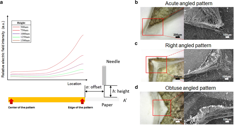
Kim et al (2018) used inkjet printing with conductive Ag nanoparticles loaded ink to form patterns on a paper as a target for near field electrospun fibers. The conductive printed pattern served as a guiding electrode for the electrospinning jet. Poly(vinylidene fluoride) (PVDF) solution was electrospun from a height of 750 µm and a 150 µm offset from the edge of the pattern. The sensitivity of the electrospinning jet towards the electric field can be seen as the fibers are stacked on the edge of the conductive pattern where the relative electric field was much higher at the edge than at its center. When the pattern lines formed acute angle, right-angle or obtuse angle, the accuracy of the deposited fibers are influenced by slight changes in the relative electric field. From acute angle to right-angle, the electric field singularity increases from the edge to the intersection between the lines. In this case, the fibers were stacked directly on the edge of the line and to the middle of the intersection. For lines forming an obtuse angle, the deposited fibers followed the edge of the lines and veered off the line at the intersection.
Zheng et al (2021) carried out further investigations on using near field electrospinning and a sharp pin guiding electrode below the collector as a means of getting highly precise and accurate fiber deposition. The role of the guiding electrode is to focus the electrical field and with near field electrospinning. Using polyethylene oxide (PEO) as the model polymer, they were able to stack up to layers of fibers to create 3D complex structures with 10 to 80 fibers layers and height of 10 to 110 µ. With solution electrospinning, residual solvents present in the deposited fibers may also facilitate migration of charges on the fiber to the ground which allow more layers of fiber to be stacked. A parameter that affects fiber placement is the collector motion velocity. A higher velocity would increase fiber placement accuracy as the polymer jet is stretched and reduces fiber diameter. A higher applied voltage also led to better fiber alignment due to greater focusing of the electric field between the nozzle and the guiding electrode. Although up to 80 fiber layers have been constructed, the effect of residual charges and the shielding of the electric field by the higher fiber layer cannot be prevented. Hence the accuracy and precision of the fiber deposition will be reduced as the layers build up. For a 60-layer fiber wall, Zheng et al (2021) reported a width of 94.3 µm and height of 102.2 µm although the fiber thickness is about 1.8 µm.
Another form of directing the electrospinning jet by modifying the electric field is using steering electrodes. Unlike the guiding electrode which is located at the collector and its effect weakened with a buildup of fibers, the steering electrode is located between the spinneret tip and the collector. It works by pushing the electrospinning jet at mid-flight hence it is not shielded by deposited fibers. Karisson et al (2021) employed a steering electrode in the direction perpendicular to the main printing direction. The deposition point of the fiber is dictated by the mechanical movement of the spinneret relative to the collector in one axis, and the steering electrode in the other axis. A CCD camera connected to a stereo microscope was used to monitor the deposition position of the fibers in real time such that the voltage to the steering electrode can be actively adjusted to steer the electrospinning jet to the correct position. Polycaprolactone was melt electrospun to determine the performance of the setup. The distance between fibers was found to affect the accuracy of the fiber placement. When the gap was 75 µm, there was little deviation between the PCL jet in flight and the fiber on the collector with and without active steering. The distance between the fibers was sufficiently large to limit the effect of residual charges on the fibers. At closer distances such as with 50 µm and 40 µm separation, active steering was able to maintain the accuracy of the fiber deposition to within a few micrometers. However, without active steering, the accuracy of the fibers deposition reduced to more than 10 µm. When the fibers were stacked to form walls, there was much less error in the positioning for active steered fibers at a fiber gap of 50 µm. However, it is not possible to get an ordered 3D structure when the fiber gap is reduced to less than 50 µm.
Charges
The charges retained on the deposited fiber have also been shown to negatively impact the ability to construct ordered structures in near-field electrospinning. Even with a conductive collector, build-up of residual charges due to stationary deposition of fibers has been shown to cause oscillation in the otherwise stable jet [Zheng et al 2010]. The effect of residual charges can also be seen when helical fibers start to form when the collector speed is unable to match the fiber ejection speed [Zheng et al 2010]. The impact of residual charge on controlled fiber deposition is magnified when a non-conducting material is used as the collector. Zheng et al (2014) showed that using a DC high voltage power supply for near field electrospinning on a polyethylene terephthalate (PET) substrate generated only randomly oriented nanofibers. The charges retained on the deposited fiber were sufficiently high to deflect the initiating jet on the tip of the nozzle. To reduce the charges on the deposited fibers, an AC high voltage power supply was used instead for near field electrospinning. This allows a vertical electrospinning jet to be maintained and collection of closely spaced fibers (about 20 µm inter-fiber spacing).
Another means of charge retention on the deposited fibers may come from the dielectric property of the solvent used. Dielectric property of a material is its ability to store electrical energy. In near field electrospinning where the objective is to accurately position the deposited fibers, a solution of high dielectric constant and low solvent evaporation may increase charge retention and have a negative impact on fiber positioning. Sadaf et al (2022) used near field electrospinning to stack up polyethylene oxide (PEO) and they hypothesized that high dielectric constant of water led to high charge retention on the deposited fibers which disrupts the positioning of the fibers. To mitigate this, methanol which has lower dielectric constant, was added into the PEO aqueous solution. Another advantage of methanol is its faster evaporation and the resultant drier deposited fibers would have lower surface charge. However when the concentration of methanol to water exceeds 40%, stacking of the fibers deteriorates. This may be due to an overall reduction in the conductivity of the solution below an optimum level for stable deposition as methanol has a much lower conductivity than water. When water is replaced with dichloromethane (DCM) in the binary solvent system, a much higher layer of fibers can be stacked. DCM has a higher conductivity than water but a much lower dielectric constant than water and methanol. Using a DCM/methanol system effectively increases the conductivity and reduces the dielectric property of the solution. Further, DCM has higher solvent evaporation compared to methanol and this also helps to reduce the amount of residual charges on the deposited fibers. However, when the concentration of DCM to methanol exceeds 60%, rapid drying of the solution resulted in disrupted electrospinning. At optimum DCM/methanol ratio 6:4, a wall aspect ratio of 191.7?was achieved which is much greater than optimum water/methanol ratio 6:4 with wall aspect ratio of 80.
Collector
In near field electrospinning, one of the risks is electrical shorting due to the proximity of the charged needle tip to the grounded collector. Any electrical shorting will disrupt the electrospinning process and result in discontinuous fiber. While using a lower voltage may reduce this risk, an alternative is to use a less conductive collector. Liu et al (2014) used a rotating glass tube with a copper foil lining at the inner surface of the tube for the collection of electrospun oriented polyvinylidene fluoride (PVDF) fiber. While initial fiber alignment was excellent, the alignment starts to deteriorate after prolonged fiber deposition which can be attributed to the presence of residual charges.
The influence of residual charges on the precision of fiber deposited is more pronounced when an insulating surface and a conductive surface were used as collectors. Choi et al (2017) used a hydrophobic and insulating acrylic substrate as collector. To increase conductivity of selected region of the collector, plasma treatment was carried out to render those region hydrophilic. The collector was placed in a high humidity environment such that the hydrophilic region will be slightly conductive due to the presence of water molecule attached to it. Near field electrospinning of polyurethane showed that on the insulating hydrophobic surface, the fibers were twisted and curved due to weak electric field profile between the emitter and the collector surface and the inability of charges to escape. In contrast, on the hydrophilic region, the fiber were placed in accordance to the movement of the emitter relative to the collector. This shows that electrical charges on the electrospinning jet needs to escape for precise deposition and even an insulating substrate with slight conductivity is crucial for ordered fiber arrangement.
The importance of collector conductivity was further demonstrated by Sadaf et al (2022). Polyethylene oxide (PEO) was used as the model polymer and unmodified silicon wafers, silicon oxide coated silicon wafers (SiO2/Si), and chromium and gold (Cr/Au) coated silicon wafers were used as the substrate material to demonstrate stacking of the near-field electrospun fibers. A continuous rotating drum collector was used to stack the electrospun fibers on top of one another with the spinneret remaining stationary. SiO2 has an insulating property and the stacking of the fibers was poor resulting in a large heap-like structure. This has been attributed to the failure to dissipate the charges on the fibers which caused dislocation of incoming fibers. Cr/Au coated substrates have much better conductivity and the result was a much straighter fiber stacked feature with a rounded top. However, individual fiber layers were not observed which may be due to relatively slow evaporation of water from the deposited fiber and causing fusion and phase separation between individual fiber layers.
Concentration
In electrospinning, it is generally agreed that with higher concentration, the diameter of the fibers increased due to greater viscosity which resist stretching. In near field electrospinning, similar observation has been reported where concentration increases, fiber diameter increased [Chang et al 2008; Zheng et al 2012]. However, in separate studies by Pan et al (2014) using poly(γ-benzyl α, l-glutamate) and Pan et al (2015) using polyvinylidene fluoride (PVDF) reported reduction in fiber diameter with increasing concentration. Pan et al (2015) attributed this to a higher charge accumulation in higher concentration PVDF solution. However, more studies need to be carried out to verify this hypothesis.
Melt Electrospinning
Significant progress has also been made in melt electrospinning and its combination with near-field electrospinning. Hochleitner et al (2015) was able to use melt electrospinning at close distance between the tip and the collector (1 to 10 mm) to produce polycaprolactone fibers with diameter of about 800 nm and stack them on top of one another to form an array of box-structures with periodicity of about 100 µm and height of 80 µm.
Multi-nozzles
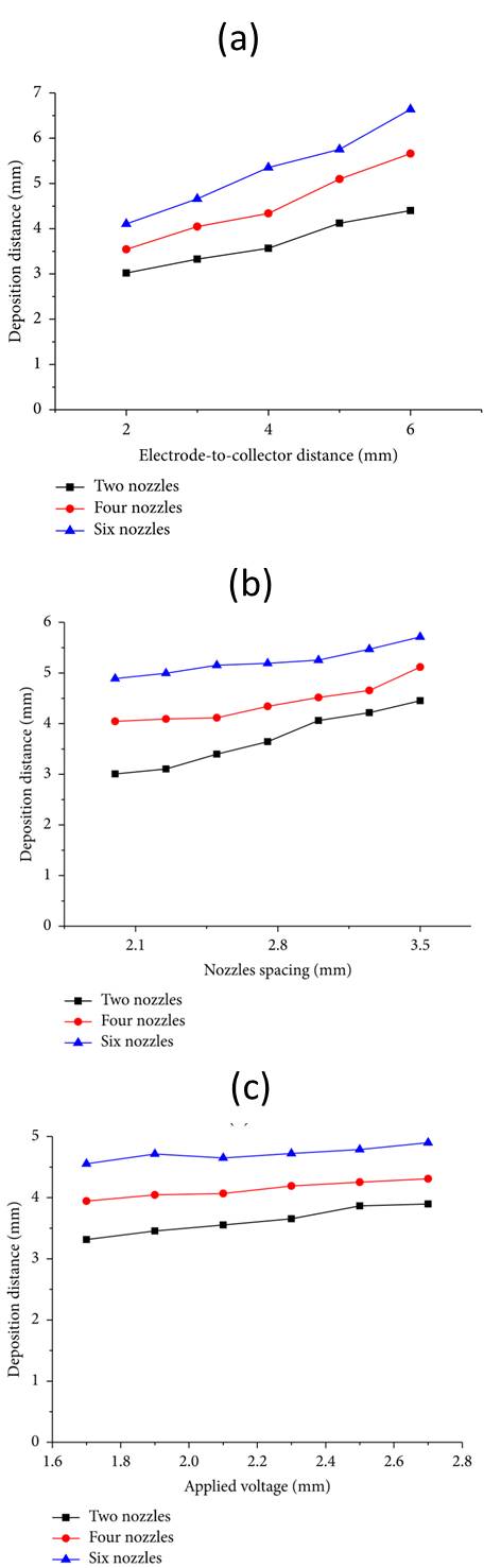
For near-field electrospinning to be used at an industrial level, a multi-nozzles system will certainly increase the output if the patterns are repeating. Therefore, it is important to understand the factors that influence precision and accurate deposition of nanofibers when multiple nozzles are used. Wang et al (2015) investigated the parameters for multiple nozzles near field electrospinning. The parameters investigated include electrode-to-collector distance ranging from 2 to 6 mm and nozzle spacing between 2.1 to 3.5 mm. From mass production of conventional electrospinning, it is known that the electric field interference between the electrospinning jets will have an impact on the process. Similarly, when there are multiple nozzles, the distance between the deposition points are larger than the distance between the nozzles. With more nozzles, the deposition distance increases. In their setup, two to six nozzles are placed in two rows. Further research is needed to determine the impact of the fiber deposition when more nozzles in other configurations are used. The accuracy and precision of the fiber deposition from each nozzle will also need to be investigated when used as a group.
Using dual nozzles setup, Wang et al (2017) did a detailed study on the parameters influencing the deposition gap between them. Parameters such as needle length, needle spacing, applied voltage and electrode to collector distance were examined. The top three dominant parameters were found to be needle spacing, electrode to collector distance and needle length. It is easy to understand the influence of needle spacing and electrode to collector distance on the gap between deposited fibers. As electrospinning jets tend to repel one another, increasing the distance between the electrode and collector allows greater divergence upon deposition. With increasing needle length, the gap between deposited fibers increases. This has been attributed to its influence on the electric field profile. With a longer needle, the vertical component of the electric field gets reduced as the charges were spread over a longer length of the needle. In an investigation by Wang et al (2018) using multiple nozzles arranged linearly, they found that the deposition distance between fibers were nearer to the inter-nozzle distance when the number of nozzles increases. This trend is the same regardless of voltage and tip to collector distance. This is contrary to an earlier investigation by another group [Wang et al 2015] which reported increasing fiber deposition distance with increasing nozzle numbers. However, it is important to note that in the earlier investigation, the nozzles were arranged in two rows while this setup is in a single row. In the study by Wang et al (2018), although the average deposition distance between the fibers were reduced with more nozzles, the coefficient of variation on deposition distance increases. That means there are greater spread in the fiber distribution.
Reduction in deposition distance between fibers when the number of nozzles increases may be attributed to electric field shielding from neighbouring nozzles. Deposition distance between fibers from marginal nozzles were greater than intermediate nozzles since the intermediate nozzles experience electric field shielding. For the same voltage, there is also less volume charge density per nozzle leading to a weaker electric field strength per nozzle. Therefore, a smaller interfiber distance was recorded for more nozzles.
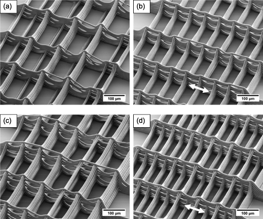
Zhang et al (2019) showed that the nozzle arrangement has a significant impact on near field electrospinning of polyethylene oxide (PEO) due to electric field interference between the nozzles. Between a linear nozzle arrangement and a 2-rows alternating nozzle arrangement, the latter has a greater electric field interference. As the electric field interference increases mutual repulsion and reduces the electric field strength near the nozzle tip, the average diameter of the resultant fiber from the 2-rows alternating nozzle arrangement is thicker than the linear arrangement. The same interference also causes greater uneven fiber deposition and variance in fiber diameter. Increasing the number of nozzles also increases electric field interference regardless of whether they are arranged linearly or 2-rows alternating. This also causes a deterioration in the quality of the fiber output. In near field electrospinning, there is a limit at which the voltage can be increased without causing electric arcing. Therefore, parameters that influence electric field interference needs to be addressed for multi-nozzles near-field electrospinning setup.
One method that has been used successfully in conventional multi-nozzles electrospinning to create a more uniform electric field strength across linearly arranged nozzles is to have the nozzle tips aligned in an arc vertically [Jiang et al 2019]. That is, the center nozzles are arranged at a height nearest to the collector and the height progressively increases towards the ends. This creates a more uniform electric field since the shielded center nozzles are now nearer to the collector. By varying the depth of the arc, the electric field strength across the nozzles can be adjusted. Comparing the electrospinning of polyethylene oxide (PEO) solution from 9 nozzles arranged linearly, between nozzle tips arranged in the same plane and in an arc, the former had solution dripping from the center nozzles while the latter showed continuous electrospinning across all 9 nozzles at optimal arc arrangement.
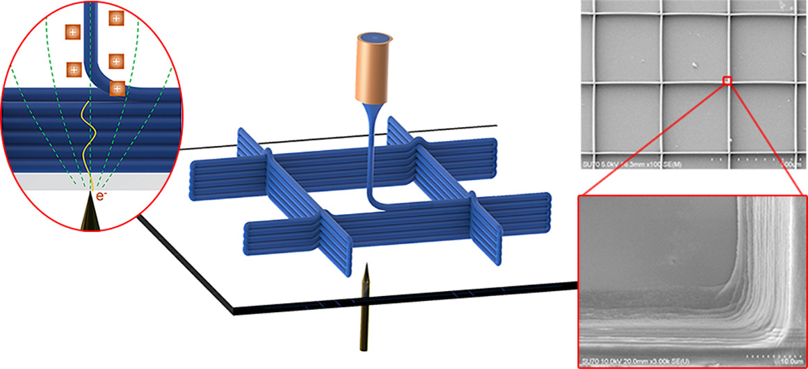
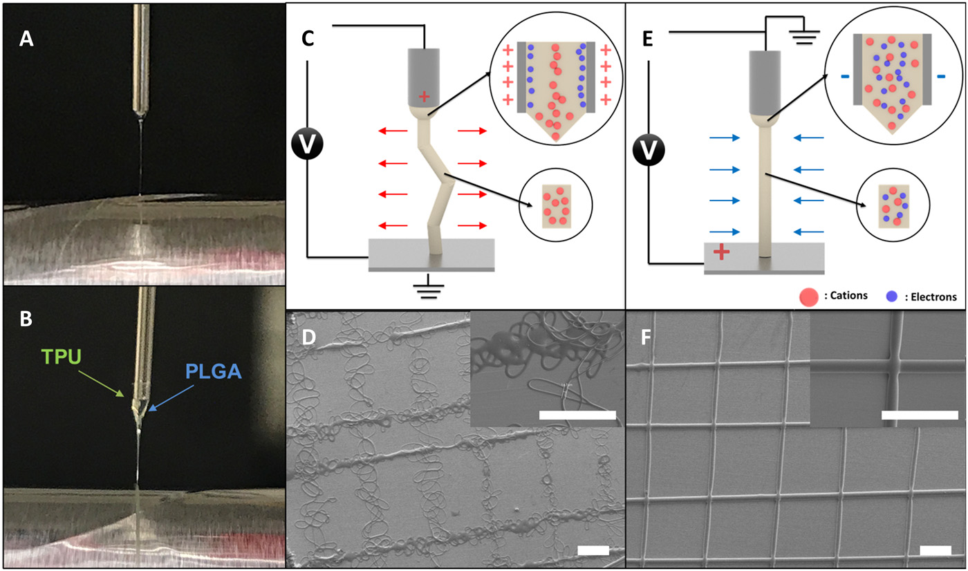
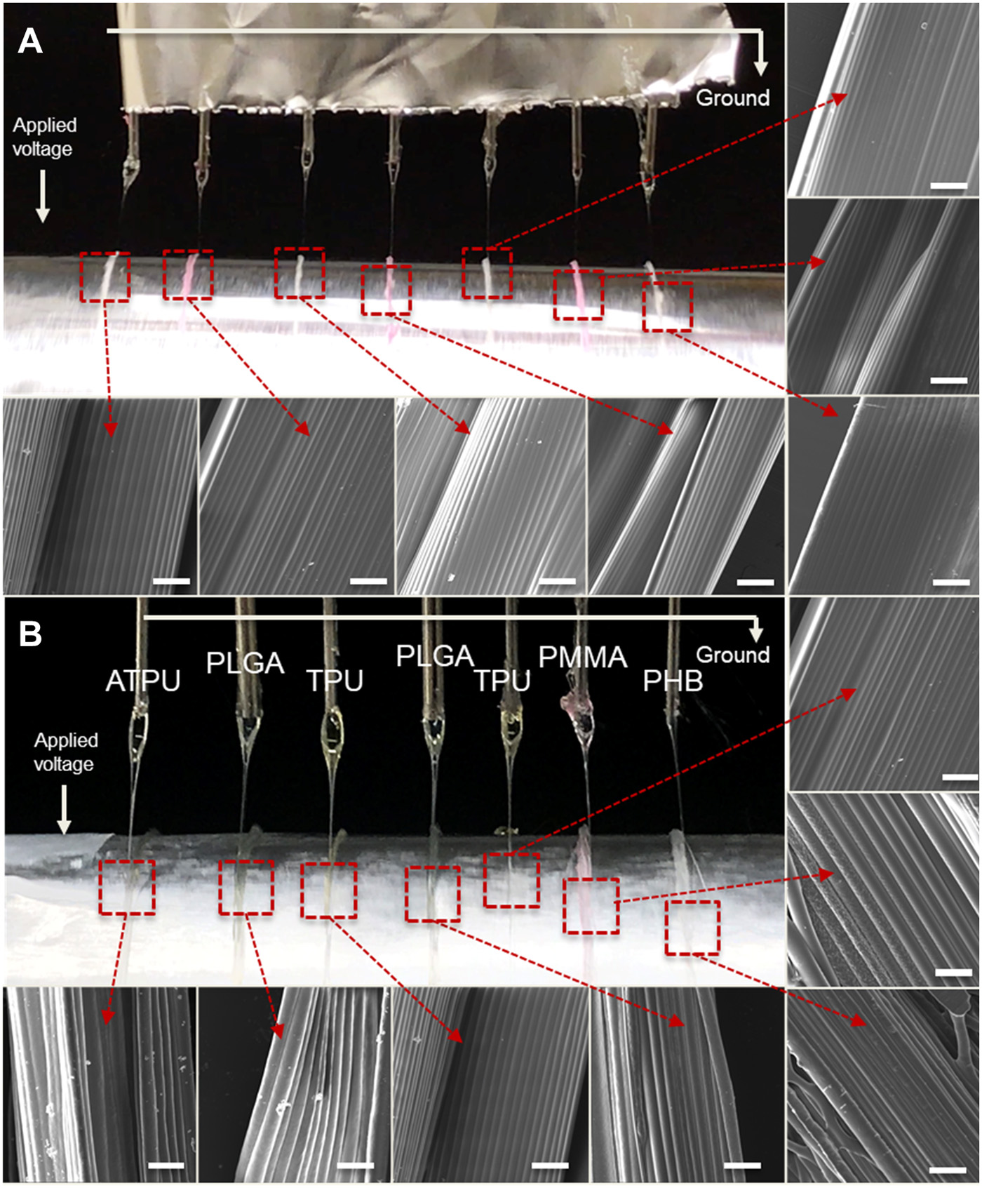
In a standard multi-nozzle setup, the high voltage is applied to the nozzles and this adds to the electric field interference within the electrospinning field. One way to reduce the charges on the nozzles is to apply the high voltage to the collector instead. Moon et al (2021) hypothesized that when a positive high voltage is applied on the collector, there is a migration of cations towards the induced negative polarity needle wall. However, as the movement of cation is slow, the presence of both cation and electrons in the electrospinning jet reduces the net interfacial charge on it. The reduced Coulombic repulsive forces on the electrospinning that causes bending instability is less than the stabilizing inertia and viscoelastic force hence there is greater jet stability. The diameter of the fibers were about 10 µm which is large for electrospun fibers. Such larger diameter also helped in the damping of the electrospinning jet.
This setup for maintaining jet stability has been tested on several polymer solutions such as TPU, PLGA, polycaprolactone (PCL) and others across multiple nozzles simultaneously at inter-nozzle distance as low as 5 mm. Each electrospinning jet was able to maintain a stable trajectory and stacked to form parallel walls.
Core-shell fibers
Near-field electrospinning has evolved to enable the production of core-shell fibers. Pan et al (2015) used a co-axial nozzle for electrospinning of poly(vinylidene fluoride) (PVDF) hollow fiber tubes. To create the hollow tubes, compressed air was ejected from the core of the nozzle during electrospinning. The core nozzle has an inner diameter of 0.63 mm while the outer nozzle has an inner diameter of 1.07 mm. The resultant fibers have a diameter of about 11 µm with inner lumen diameter of about 3 µm.
Assisted Airflow
Assisted airflow electrospinning or electroblowing uses a curtain of blowing air around the electrospinning nozzle tip to facilitate jet initiation and stretching of the jet. This reduces the voltage required for electrospinning and also helps to direct the electrospinning jet. When used with near field electrospinning, this increases the precision and accuracy of the fiber deposition. However, unlike most near field electrospinning setup, the distance between the nozzle tip and collector cannot be too close or there will be air turbulence from the blowing air bouncing off the solid substrate. Jiang et al (2018) showed that the optimum distance for assisted airflow near field electrospinning was 2 mm for polyethylene oxide (PEO) solution. Both precision and accuracy were improved with assisted airflow. When combined with optimised collector velocity, positioning errors of less than 5% has been printed for complex patterns.
Other Variations
Some researchers have used other unique materials and devices to create near field electrospinning. Coppola et al (2020) constructed an alternative form of near-field electrospinning, named, pyro-electrohydrodynamic tethered electrospinning. In their setup, a pyroelectric material, lithium niobate (LN) crystal plate was used to generate the electric field. This LN crystal plate was placed behind a glass microslide collector. A small drop of poly(lactic-co-glycolic acid) (PLGA) solution was placed at a distance of less than 1 mm from the crystal plate. Heating of the lithium niobate (LN) crystal plate generates charges and at sufficiently high voltage, a single stable electrospinning jet would erupt from the PLGA solution droplet. The target collector would move as the fiber deposited on it to form the desired structure. The resultant fiber has a diameter between 10 µm < d < 30?µm. The precision of the fiber deposition is such that the multiple layers of fibers can be stacked on top of one another. A wall made of 10 fiber layers was constructed with good superimposition and homogenous stacking, no spaces or defects.
Published date: 06 October 2015
Last updated: 27 June 2023
▼ Reference
-
Bisht G S, Canton G, Mirsepassi A, Kulinsky L, Oh S, Dunn-Rankin D, Madou M J. Controlled Continuous Patterning of Polymeric Nanofibers on Three-Dimensional Substrates Using Low-Voltage Near-Field Electrospinning. Nano Lett. 2011; 11: 1831.
-
Calzado-Delgado M, Guerrero-Pérez M O, Yeung K L. A new versatile x-y-z electrospinning equipment for nanofiber synthesis in both far and near field. Scientific Reports 2022; 12: 4872.
Open Access
-
Camillo D D, Fasano V, Ruggieri F, Santucci S, Lozzi L, Camposeo A, Pisignano D. Near-field electrospinning of conjugated polymer light-emitting nanofibers. Nanoscale 2013; 5: 11637.
Open Access
-
Chang C, Limkrailassiri K, Lin L. Continuous near-field electrospinning for large area deposition of orderly nanofiber patterns. Appl Phys Lett 2008; 93:123111.
-
Choi W, Kim G H, Shin J H, Lim G, An T. Electrospinning onto Insulating Substrates by Controlling Surface Wettability and Humidity. Nanoscale Research Letters 2017; 12:610. Open Access
-
Coppola S, Nasti G, Vespini V, Ferraro P. Layered 3D Printing by Tethered Pyro-Electrospinning. Advances in Polymer Technology 2020; 2020: 1252960.
Open Access
-
George D, Garcia A, Pham Q, Perez M R, Deng J, Nguyen M T, Zhou T, Martinez-Chapa S O, Won Y, Liu C, Lo R C. Fabrication of patterned graphitized carbon wires using low voltage near-field electrospinning, pyrolysis, electrodeposition, and chemical vapor deposition. Microsyst Nanoeng 2020; 6: 7.
Open Access
-
Gupta A, Seifalian M, Ahmad Z, Edirisinghe M J and Winslet M C. Novel electrohydrodynamic printing of nanocomposite biopolymer scaffolds. J. Bioact. Compat. Polym. 2007; 22: 265.
-
Hochleitner G, Jungst T, Brown T D, Hahn K, Moseke C, Jakob F, Dalton P D, Groll J. Additive manufacturing of scaffolds with sub-micron filaments via melt electrospinning writing. Biofabrication 2015; 7: 035002.
Open Access
-
Huang Y A, Duan Y, Ding Y, Bu N, Pan Y, Lu N, Yin Z. Versatile, kinetically controlled, high precision electrohydrodynamic writing of micro/nanofibers. Science Reports 2014; 4: 5949.
Open Access
-
Jiang J, Wang X, Li W, Liu J, Liu Y, Zheng G. Electrohydrodynamic Direct-Writing Micropatterns with Assisted Airflow. Micromachines 2018; 9: 456.
Open Access
-
Jiang J, Zheng G, Wang X, Li W, Kang G, Chen H, Guo S, Liu J. Arced Multi-Nozzle Electrospinning Spinneret for High-Throughput Production of Nanofibers. Micromachines 2020; 11: 27.
Open Access
-
Kameoka J, Craighead H G. Fabrication of oriented polymeric nanofibers on planar surfaces by electrospinning Appl. Phys. Lett. 2003; 83: 371.
-
Karlsson A, Bergman H, Johansson S. Active real-time electric field control of the e-jet in near-field electrospinning using an auxiliary electrode. Journal of Micromechanics and Microengineering 2021; 31: 035001
Open Access
-
Kim J, Maeng B, Park J. Characterization of 3D electrospinning on inkjet printed conductive pattern on paper. Micro and Nano Systems Letters 2018, 6:12.
Open Access
-
King WE III, Gillespie Y, Gilbert K, Bowlin GL. Characterization of Polydioxanone in Near-Field Electrospinning. Polymers (Basel). 2019; 12(1): 1.
Open Access
-
Liu Z H, Pan C T, Lin L W, Huang J C, Ou Z Y. Direct-write PVDF nonwoven fiber fabric energy harvesters via the hollow cylindrical near-field electrospinning process. Smart Mater. Struct. 2014; 23: 025003.
-
Min S Y, Kim T S, Kim B J, Cho H C, Noh Y Y, Yang H C, Cho J H, Lee T W. Large-scale organic nanowire lithography and electronics. Nature Communications 2013; 4: 1773.
-
Moon S, Jones M S, Seo E, Lee J, Lahann L, Jordahl J H, Lee K J, Lahann J. 3D jet writing of mechanically actuated tandem scaffolds. Science Advances 2021; 7
Open Access
-
Pan C T, Yen C K, Wang S Y, Lai Y C, Lin L, Huang J C, Kuo S W. Near-field electrospinning enhances the energy harvesting of hollow PVDF piezoelectric fibers. RSC Adv 2015; 5: 85073.
-
Pan C T, Yen C K, Liu Z H, Li H W, Kuo S W, Lu Y S, Lai Y C. Poly(γ-benzyl α, l-glutamate) in Cylindrical Near-Field Electrospinning Fabrication and Analysis of Piezoelectric Fibers. Sensors and Materials 2014; 26: 63.
-
Sadaf A, Elter M, Mager D, Bunz U H F, Islam M, Korvink J G. Wall Microstructures of High Aspect Ratio Enabled by Near-Field Electrospinning. Advanced Engineering Materials 2022; 24: 2101740.
Open Access
-
Song C, Rogers J A, Kim J M, Ahn H. Patterned Polydiacetylene-Embedded Polystyrene Nanofibers Based on Electrohydrodynamic Jet Printing. Macromolecular Research 2015; 23: 118.
-
Sun D, Chang C, Li S, Lin L. Near-field electrospinning Nano Lett. 2006; 6: 839.
-
Wang H, Huang S, Liang F, Wu P, Li M, Lin S, Chen X. Research on Multinozzle Near-Field Electrospinning Patterned Deposition. Journal of Nanomaterials 2015; 2015: 529138.
Open Access
-
Wang Z, Chen X, Zeng J, Liang F, Wu P. Controllable deposition distance of aligned pattern via dual-nozzle near-field electrospinning. AIP Advances 2017; 7: 035310.
Open Access
-
Wang Z, Chen X, Zhang J, Lin Y J, Li K, Zeng J, Wu P, He Y, Li Y, Wang H. Fabrication and evaluation of controllable deposition distance for aligned pattern by multi-nozzle near-field electrospinning. AIP Advances 2018; 8: 075111.
Open Access
-
Xu J, Abecassis M, Zhang Z, Guo P, Huang J, Ehmann K, Cao J. Accuracy Improvement of Nano-fiber Deposition by Near-Field Electrospinning. IWMF2014, 9th International Workshop on Microfactories. October 5 - 8 2014, USA.
Open Access
-
Xue N, Li X, Bertulli C, Li Z, Patharagulpong A, Sadok A, Huang Y Y S. Rapid Patterning of 1-D Collagenous Topography as an ECM Protein Fibril Platform for Image Cytometry. PLoS ONE 9(4): e93590. doi:10.1371/journal.pone.0093590.
Open Access
-
Zhang J, Wang H, Wang Z, Yao H, Xu G, Yan S, Zeng J, Zhu X, Deng J, Zhuo S, Zeng J. Influence and evaluation of array-nozzle geometry on near- field electrospinning direct writing. Journal of Engineered Fibers and Fabrics 2019 Article in press
Open Access
-
Zheng G, Jiang J, Wang X, Li W, Yu Z, Lin L. High-aspect-ratio three-dimensional electrospinning via a tip guiding electrode. Materials & Design 2921; 198: 109304
Open Access
-
Zheng G, Li W, Wang X, Wu D, Sun D, Lin L. Precision deposition of a nanofibre by near-field electrospinning. J. Phys. D: Appl. Phys. 2010; 43: 415501.
-
Zheng J Y, Liu H Y, Wang X, Zhao Y, Huang W W, Zheng G F, Sun D H. Electrohydrodynamic Direct-Write Orderly Micro/Nanofibrous Structure on Flexible Insulating Substrate. Journal of Nanomaterials 2014; 708186 (7 pages)
Open Access
-
Zheng J, Long Y Z, Sun B, Zhang Z H, Shao F, Zhang H D, Zhang Z M, Huang J Y. Polymer nanofibers prepared by low-voltage near-field electrospinning. Chin. Phys. B. 2012; 21: 048102.
▲ Close list