▼ Reference
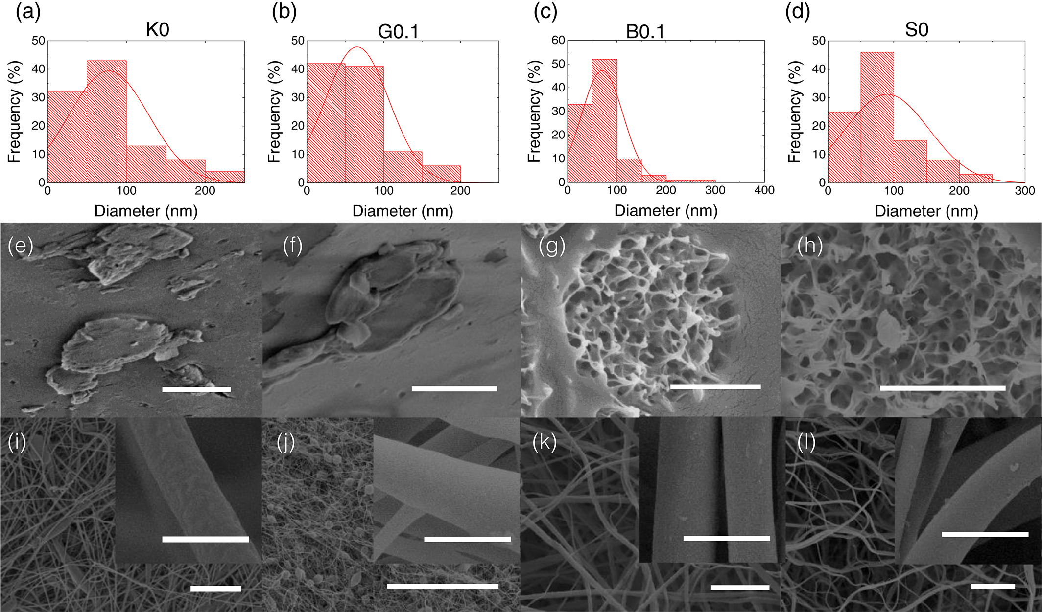
- Abolhasani M M, Azimi S, Mousavi M, Anwar S, Amiri M H, Shirvanimoghaddam K, Naebe M, Michels J, Asadi K. Porous graphene/poly(vinylidene fluoride) nanofibers for pressure sensing. Journal of Applied Polymer Science 2022; 139: 51907. Open Access
- Gupta A, Saquing C D, Afshari M, Tonelli A E, Khan S A, Kotek R. Porous Nylon-6 Fibers via a Novel Salt-Induced Electrospinning Method. Macromolecules 2009; 42: 709.
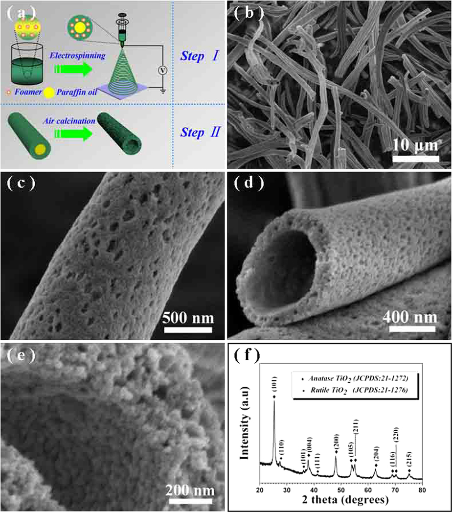
- Hou H, Shang M, Wang L, Li W, Tang B, Yang W. Efficient Photocatalytic Activities of TiO2 Hollow Fibers with Mixed Phases and Mesoporous Walls. Scientific Reports 2015; 5: 15228. Open Access
- Li J, Qiao H, Du Y, Chen C, Li X, Cui J, Kumar D, Wei Q. Electrospinning Synthesis and Photocatalytic Activity of Mesoporous TiO2 Nanofibers. The Scientific World Journal 2012; 2012: 154939. Open Access
- Mao F Y, Wang Y, Fu K, Jin J H, Yang S L, Li G. The Influence of Porous Features on the Electrochemical Performance of Its Supported Platinum Catalyst in Porous Carbon Nanofibers. Journal of Materials Science and Chemical Engineering 2017; 5: 10. Open Access
- Mondal K, Ali M Z, Argrawal V V, Malhotra D, Sharma A. Highly sensitive biofunctionalized meosoporous TiO Nanofiber Based Interface for Biosensing. ACS Appl. Mater. Interfaces. 2014; 6: 2516.
- Nguyen T A, Jun T S, Rashid M, Kim Y S. Synthesis of mesoporous tungsten oxide nanofibers using the electrospinning method. Materials Letters 2011; 65: 2823.
- Song X, Wang Z, Liu Y, Wang C, Li L. A highly sensitive ethanol sensor based on mesoporous ZnO-SnO2 nanofibers. Nanotechnology 2009; 20: 075501.
- Taha A A, Qiao J, Li F, Zhang B. Preparation and application of amino functionalized mesoporous nanofiber membrane via electrospinning for adsorption of Cr3+ from aqueous solution. J Environ Sci (China) 2012; 24: 610.
- Teng M, Qiao J, Li F, Bera P K. Electrospun mesoporous carbon nanofibers produced from phenolic resin and their use in the adsorption of large dye molecules. Carbon 2012; 50: 2877.
- Wang W, Yuan Q, Chi Y, Shao C L, Li N, Li X T. Preparation and Photocatalysis of Mesoporous TiO2 Nanofibers via an Electrospinning Technique. Chem. Res. Chinese Universities 2012; 28: 727.
- Yu D, Chen C, Xie S, Liu Y, Park K, Zhou X, Zhang Q, Li J, Cao G. Mesoporous vanadium pentoxide nanofibers with significantly enhanced Li-ion storage properties by electrospinning. Energy Environ Sci 2011; 4: 858.
- Zaarour B, Zhu L, Huang C, Jin X. Fabrication of a polyvinylidene fluoride cactus-like nanofiber through one-step electrospinning. RSC Adv., 2018, 8, 42353. Open Access
▼ Credit and Acknowledgement
Author
Wee-Eong TEO View profile
Email: weeeong@yahoo.com
