Electrospinning may be used to produce fibers with different compositions and material distribution. This is due to the relative ease of forming a Taylor Cone to initiate electrospinning on different types of nozzle constructions. Apart from standard single orifice nozzles, the next most commonly used nozzle design will be coaxial nozzles for electrospinning core-shell fibers. Other types of nozzle design have also been used including triaxial, side-by-side orifice nozzles and multi-core nozzles. These nozzle designs enable fibers with different compositions and profiles to be electrospun adding to the range of properties and characteristics exhibited by electrospun fibers.
A coaxial nozzle design enables two different materials to be dispensed for electrospinning of nanofibers. Such fibers are known as core-shell fibers as the core and sheath materials that made up the fibers are made from two distinct materials. This is particularly useful in drug delivery applications where the drug is typically loaded in the core such that the sheath provides a barrier to reduce the drug release rate. For this setup, only one of the materials needs to be electrospinninable to carry the drug. When the core-material is made out of low molecular material or oil, these can be easily extracted to form hollow fibers.
Expanding the range of material layers in a fiber, triaxial nozzles have been developed. Panzavolta et al (2016) prepared calcium phosphate nanoparticles inside gelatine nanofibers through a triaxial needle. For this setup, the outermost channel is the gelatine solution, the intermediate channel contains calcium solution and the central channel contains phosphate solution. As all three solutions were being ejected, the phosphate and calcium solution mixed and formed calcium phosphate nanoparticles while the gelatine solution encapsulated the resultant nanoparticles and electrospins from the needle tip. TEM analysis revealed the presence of nanoparticles at the core of the fibers but they were not uniformly distributed throughout the length of the fiber.
To better control drug release from electrospun fibers, Liu et al (2022) used a triaxial nozzle for electrospinning of curcumin encapsulated in cellulose acetate (CA). In their setup, the core was loaded with CA with curcumin, the middle section was loaded with pure CA and the outermost sheath was covered with a solvent mixture of ethanol, DMF, and acetone. The outermost coverage by the solvents help to maintain the stability of the electrospinning process. The flow rate of the middle section containing pure CA was varied to control the thickness of the wall covering the innermost CA loaded fibers. The electrospun fibers from blended curcumin in CA, showed an initial burst release. The introduction of a layer covering the drug loaded core prevented initial burst release and a thicker sheath layer showed an almost linear release from 12 to 36 h.
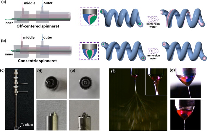
A triaxial nozzle may also be used to construct hollow fibers or grooved fibers depending on the positioning of the inner channels. Zhao et al (2021) used a tri-fluid electrospinning technique where a tri-axial nozzle was used for the extrusion of different solutions. The three working components for their setup were cellulose acetate (CA), thermoplastic polyurethane (TPU), and polyvinylpyrrolidone (PVP). CA and TPU were the outer and middle components and PVP was the inner sacrificial component to be removed for the generation of hollow or groove structure. CA and TPU were selected due to their significant difference in modulus which encouraged the formation of helical nanofibers. For the formation of groove structure, the channels of the tri-axial spinneret were off-centered. With the core channel off-set to one side, the water soluble PVP core will be nearer to one side of the fiber. After the fibers were immersed in water, dissolution of the PVP formed a groove along one side of the fiber. To maintain a helical shape of the fiber, the flow rate of the PVP solution core needs to be sufficiently low as higher PVP solution flow rate results in mostly straight fibers. This is probably due to greater core thickness at higher core flow rate which resists bending of the electrospinning jet.
Bohr et al (2022) used a triaxial nozzle to demonstrate the possibility of constructing a triaxial perovskite composite fiber which may lead to the development of energy producing fabric. The three materials are copper(I) thiocyanate (CuSCN) layer in the core as hole transport material, an intermediate shell of the perovskite absorber layer (MAPbI3) and zinc oxide as electron transport material in the outermost shell. All three materials were electrospun in their respective precursor form into fibers followed by heat treatment. To ensure that the electrospun fibers deposited on the collector are dry, the collector was heated to 130 °C and further heat drying was carried out after fiber collection to remove any residual solvents. A functional electrical generating solar fiber would probably require more than these three materials layers and a means to introduce conducting layers in the fiber as well.
Wang et al (2023) showed the benefits of electrospinning fibers with multiple layers to obtain multi-functional properties. In their triaxial electrospun fibers, the core was a magnetic material, CoFe2O4/polymethyl methacrylate (PMMA), the intermediate layer was conductive polyaniline (PANI)/PMMA and a Tb(acac)3bpy/PMMA insulated-fluorescent shell layer. This multi-layered fiber was electrospun through a tri-axial nozzle with the individual material extruded through their corresponding opening. The resultant electrospun fiber took the form of a microbelt with width of about 13 µm and the thickness of 4.45 µm. Of the materials properties, the fluorescent material was the most sensitive to the presence of other materials. When all three functional materials, CoFe2O4 nanoparticles, PANI and Tb(acac)3bpy were mixed together with PMMA and electrospun as a single fiber, the fluorescence was the weakest due to the absorption of excitation and emission lights by CoFe2O4 nanoparticles and PANI. Similarly conductivity of the fiber was the weakest when PANI was blended with other functional materials due to the interference with charge transfer. Therefore, to ensure high functional output from respective materials, it is desirable to keep the functional materials separated on the same fiber.
Quad-axial nozzle electrospinning may be one option but with each additional layer, it will be a greater challenge to maintain a continuous layer through the length of the fiber.
In some applications, it may be desirable that the components are equally expressed and exposed on the surface of the fiber. In this case, a side-by-side bicomponent setup would be an advantage. Unlike core-shell or blended fibers, a side-by-side bicomponent fiber will ensure that both components have equal exposure on the surface. A typical setup to generate side-by-side bicomponent fiber using electrospinning is to use a nozzle consisting of split outlets running side-by-side. The two materials are carried through two separated channels until they converge at the nozzle outlet. In electrospinning using a split nozzle, controlling the electric field plays a more important role than a single orifice nozzle. When the distance between the nozzle tip and the collector is too far, the electric field strength is insufficient to initiate electrospinning. However, when the distance is too near, two separate Taylor cones were formed, coming from each of the openings [Gupta and Wilkes 2003]. Therefore, an optimum distance between the nozzle tip and the collector is needed to maintain a steady single electrospinning jet.
Side-by-side bicomponent fiber may yield interesting mechanical behaviour due to the physical characteristics of the fiber. Lin et al (2005) showed that using polyacrylonitrile (PAN) and polyurethane (PU) as the two materials in their bi-component system, they were able to construct curly and helically crimped fibers. This behavior has been attributed to differential shrinkage within the fibers which causes one of the components to compress. Increasing the amount of PAN by increasing its flow rate leads to less curly nanofibers while the converse is true when the PU content was increased. Chen et al (2009) showed that very curly nanofibers may work as a nanospring and this may influence the mechanical properties of the resultant mat. Using poly(m-phenylene isophthalamide) (Nomex) and thermoplastic polyurethane (TPU), they found that the net elastic force of the aligned nanospring fibers from side-by-side bicomponent fiber showed a higher elongation, higher toughness and higher modulus than fibers without nanospring. Fibers with and without the nanospring were both side-by-side bicomponent fibers. To obtain aligned fibers without nanospring, the collector was set at a higher rotation speed while aligned fibers with nanospring were collected with lower rotation speed.
While a split-nozzle is often used to electrospin side-by-side component fibers, this is not always the case. Schmidt et al (2025) used a split nozzle to create core-shell beads on string (BOS) fibers. The beads were made of a random copolymer of N-isopropylacrylamide (NIPAM) with N,N-(2-(diethylamino)ethyl)acrylamide (DEAAm) and N-(4-benzoylphenyl)acrylamide (BPAA), denoted as PIDB while the string was made of polystyrene (PS). Both materials need to be sufficiently incompatible in terms of solubility to produce the BOS fibers. During electrospinning, as both solutions came into contact as they were extruded through the respective side of the nozzle, the solutions mixed and PIDB beads were arranged in regular distances along the PS core fiber. PS solution can be drawn into fibers by electrospinning hence it formed a continuous string as it was extruded. The PIDB concentration was kept sufficiently low such that it formed beads on string fiber on its own and when merged with PS solution, it formed PIDB beads along a PS core string fiber. It is unclear why this did not result in a side-by-side bicomponent fiber but instead, a core-shell fiber. It may be due to the presence of beads that caused one solution to wrap around the other solution during electrospinning.
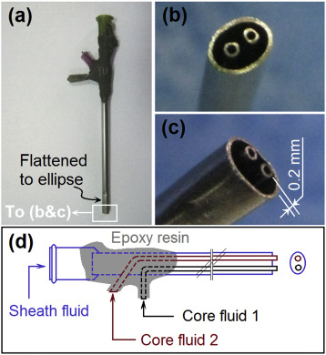
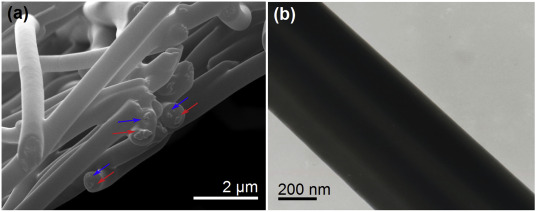
An interesting development in multi-chamber nozzle electrospinning is the multi-core nozzle. For this setup, there are more than one core chambers surrounded by a sheath wall. The resultant fiber contained two separate cores encapsulated within a single sheath material. Chang et al (2020) demonstrated electrospinning of this nozzle setup to obtain multi-core fibers for the purpose of drug delivery. Eudragit of different molecular weight was used as the sheath and core materials. For dual cores, an active ingredient, paracetamol, was added to Eudragit. The resultant electrospun fibers have an average diameter of 660 nm. From their SEM and TEM images, it is possible to see two distinct cores within a single sheath material.
Published date: 3 November 2020
Last updated: 13 May 2025
▼ Reference
-
Bohr C, Le K, Fischer T, Mathur S. Triaxial Perovskite Composite Fibers Spinning the Way to Flexible Solar Cells. Adv. Eng. Mater. 2022; 24: 2100773.
Open Access
-
Chang S, Wang M, Zhang F, Liu Y, Liu X, Yu D G, Shen H. Sheath-separate-core nanocomposites fabricated using a trifluid electrospinning. Materials & Design 2020; 192: 108782.
Open Access
-
Chen S, Hou H, Hu P, Wendorff J H, Greiner A, Agarwal S. Effect of Different Bicomponent Electrospinning Techniques on the Formation of Polymeric Nanosprings. Macromol. Mater. Eng. 2009; 294: 781.
-
Gupta P, Wilkes G L. Some investigations on the fiber formation by utilizing a side-by-side bicomponent electrospinning approach. Polymer 2003; 44: 6353.
-
Lin T, Wang H, Wang X. Self-Crimping Bicomponent Nanofibers Electrospun from Polyacrylonitrile and Elastomeric Polyurethane. Adv. Mater. 2005; 17: 2699.
-
Liu Y, Chen X, Gao Y, Liu Y, Yu D, Liu P. Electrospun Core-Sheath Nanofibers with Variable Shell Thickness for Modifying Curcumin Release to Achieve a Better Antibacterial Performance. Biomolecules. 2022 Jul 29;12(8):1057.
Open Access
-
Panzavolta S, Gualandi C, Fiorani A, Bracci B, Focarete M L, Bigi A. Fast Coprecipitation of Calcium Phosphate Nanoparticles inside Gelatin Nanofibers by Tricoaxial Electrospinning. Journal of Nanomaterials 2016; 2016: Article ID 4235235
Open Access
-
Schmidt M, Riecken C, Zussman E, Agarwal S, Schmalz H, Greiner A. Regio-Selective Functionalisation of Electrospun Materials at the Microscale. Advanced Materials Interfaces 2025; 12: 2400666.
https://advanced.onlinelibrary.wiley.com/doi/10.1002/admi.202400666 Open Access
-
Wang Y, Qi H, Xie Y, Shao H, Yang L, Sun D, Ma Q, Yu W, Dong X. Design and one-pot direct electrospinning construction of high-performance magnetic@conductive@fluorescent tri-coaxial microbelts and array. Polymer Testing 2023; 117: 107857.
Open Access
-
Zhao T, Zheng Y, Zhang X, Teng D, Xu Y, Yongchun Zeng Y. Design of helical groove/hollow nanofibers via tri-fluid electrospinning. Materials & Design 2021; 205: 109705.
Open Access
▲ Close list