Most lab-based electrospinning setups comprises of a nozzle spinneret for dispensing of the solution. Despite the emergence of nozzle-less electrospinning techniques especially in mass production electrospinning, nozzle-based electrospinning still retains some advantages such as better charge concentration and nozzle variations for improving electrospinning or fabricating hybrid fibers. In most lab-based electrospinning setup, a hypodermic needle with a flat tip is used as the electrospinning nozzle. However, electrospinning may still proceed with other needle tip configurations. A flat tip is generally preferred as it provides a flat surface for the formation of a stable Taylor cone with little oscillation of the jet compared to chamfered tip needle [Ksapabutr et al 2005]. At higher feed-rate, it was found that a flat tip needle is more prone to generating multiple electrospinning jets compared to chamfered tip needle [Ksapabutr et al 2005]. Parameters such as nozzle diameter has been covered elsewhere and will not be covered here. Instead, other improvements and variations of nozzle design shall be discussed.
As a class, the coaxial nozzle is the most widely used design in electrospinning. While most commonly used for spinning core-shell nanofibers through injection of different solution through the core and shell of the nozzle, this design have also been used to inject solvent through the shell cavity to maintain spinnability of the solution (Read more). Injection of solvent through the shell of a co-axial electrospinning setup was also found to affect the cross-sectional profile of the resultant fibers. When electrospinning Eudragit L100 nanofibers using conventional single nozzle, the fibers produced were found to have a flat/ribbon cross-sectional profile. This is attributed to the formation of a thin wall/skin due to rapid evaporation of ethanol on the surface of the electrospinning jet. Subsequent evaporation from the core of the electrospinning jet causes the thin wall to collapse and form flat fibers. To produce round fibers, Yu et al (2014) injected solvent through the shell of a co-axial nozzle during electrospinning such that it delays the evaporation from the surface of the main electrospinning jet which allows smoother mass transfer of the solvents from the core to the atmosphere. This delay also enables more stretching of the electrospinning jet and thus smaller diameter fibers can be produced. Another use of the coaxial design is to allow incorporation of air jet surrounding the core spinning nozzle to facilitate and improve jet initiation (Read more).
Coaxial nozzle has also been used as a simple means to construct fiber-nanoparticles hybrid films where the fiber is produced by electrospinning and the nanoparticles by electrospraying using the same nozzle. Du et al (2023) demonstrated this by using a coaxial nozzle with the inner orifice made of metal and the outer sheath made of polyethylene. The core and sheath solutions were fed separately and charging of both solutions were via the inner metal orifice. The electrospinnable solution was to be fed through the core while the non-electrospinnable solution was to be fed through the sheath. For electrospinning of the inner core solution, only the inner core solution was fed and for electrospraying, only the outer sheath solution was fed. With this simple alternating of solution feeding either through the inner core or outer sheath solution, electrospinning and electrospraying respectively can be carried out. This setup also allows routine core-shell electrospinning by feeding both solutions simultaneously.
Electrospinning involves introducing charges to the solution under an electric field. In conventional electrospinning setup, a metallic nozzle is used for dispensing the solution and application of charge is through the nozzle. The sharp edge of the exposed nozzle results in point discharge where the air around the nozzle tip gets ionized. Experiments have shown that even without any solution present, an electrical current can be picked up at the collector [Collins et al 2012, Lien 2013].
The concentration of charges for a sharp tip needle in electrospinning have been shown to produce nanofibers with greater surface residual charges compared to a blunt needle. The greater residual charges were attributed to Corona discharge at the sharp tip. However, the greater charge concentration at the sharp tip may trigger multiple and unstable jets leading to beaded or poor quality nanofibers [He et al 2025]. Therefore, blunt tip needles are more commonly used in electrospinning.
Li et al (2014) hypothesized that having a material that lowers the interfacial tension between the solution and the nozzle and retarding loss of electrical energy to the atmosphere, coated on the outer surface of the nozzle will lead to more efficient electrospinning. Using polyvinyl chloride (an antistatic polymer) as a coating over the stainless steel nozzle, their experiment showed that for the coated nozzle, the deflection angle of the electrospinning jet is larger, Taylor cone is smaller and the stable section of the jet shorter. These observations suggest better transfer of electrical charges to the solution from the coated nozzle compared to the purely stainless steel nozzle [Li et al 2014]. Hohman et al (2001) suggested that bending instability will be greater when the charges on the jet contribute more to the local electric field than the tangential electric field from the spinneret. With the insulated coating, the tangential electric field from the spinneret will be reduced and a shorter stable jet section can be expected. Since thinning of the electrospinning jet to the nanometer dimension comes from the longer stretching distance as a result of the bending instability, an earlier transformation to the unstable phase by the electrospinning jet is likely to result in a thinner fiber [Zhou et al 2013]. Using an epoxy coating over the electrospinning spinneret, Li et al (2013) showed that the diameter of electrospun ethyl cellulose (EC)/ketoprofen (KET) blended fibers was smaller than the fibers from uncoated metal spinneret. Having an outer coating would also reduce loss of charges through edge emission and ionization of air [Collins et al 2012].
An alternative method to achieve this is to use a non-conducting nozzle and charging of the solution using an electrode inserted into the solution. Without any solution present, no electrical current was detected at the collector providing the evidence that there was none or very few ionization of the air [Lien 2013]. Lien (2013) tested the influence of having an external insulating cover over a Teflon nozzle and charging of the solution by inserting an electrode into the solution on the current flowing through the collector. The study showed negligible difference in current with and without the insulating cover.
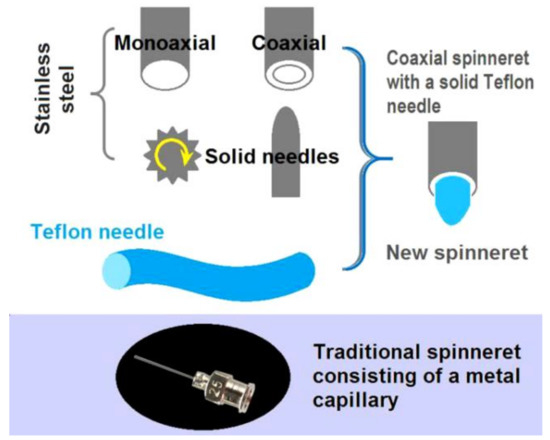
Reduction in the power consumption of the electrospinning process can be achieved by modifying the nozzle design. For initiation of electrospinning jet, energy is expended to overcome the surface tension and capillary action of the solution. Kang et al (2020) showed that by inserting a solid Teflon needle in the nozzle, they were able to reduce the power needed for electrospinning. To further reduce energy loss to the environment, much of the metal nozzle was covered with epoxy resin except a short section at the tip for connecting to incoming power. Using polyvinylpyrrolidone (PVP) as the model solution for testing the nozzle design, they found that having a solid Teflon needle in the nozzle for electrospinning and insulation of the tip, only uses 54% of the power of conventional metal nozzles. This was calculated from the reduced voltage required for steady electrospinning and lower current. Such power reduction has been attributed to the hydrophobic Teflon inner rod that reduces the capillary counter force and the concentration of the applied charges to the solution at the tip. Evidence of more efficient charging of the electrospinning jet can be seen by a longer stable jet phase and larger spiraling radius of the electrospinning jet with the modified nozzle.
An important function of the nozzle is to maintain the shape of the Taylor cone and to reduce the capillary force that is pulling back the solution. McCarthy et al (2021) installed a 3D printed needle cap on the tip of the electrospinning nozzle to improve Taylor cone stability at higher solution feed rate. Due to the conical shape of the cap, it reduces excess solution from wicking up the outer surface of the nozzle due to capillary action. The shape of the cap also widens the meniscus diameter of the Taylor cone and a wider meniscus diameter has been shown to give a more stable jet. Without the cap, a pendant-shaped Taylor cone is formed which is less stable compared to a conical-shaped Taylor cone. With the cap, the Taylor cone maintained a conical-shape even at maximum flow rate.
In nozzle-based electrospinning, the solution flows through a capillary or orifice. Using needle is just one form of it. There are other methods using this concept especially for mass production. A tube nozzle has been used by Fang et al (2017) for mass production electrospinning. The nozzle setup is made of a tube with an array of holes along its length. This setup was able to successfully increase the output of electrospun SU-8, photopatternable epoxy. For near field electrospinning, Pan et al (2017) came out with a circuit board design with solder balls as the nozzle. The orifice was created by a precision driller. A chamber body completes the setup for electrospinning polyvinylidene fluoride (PVDF) fiber.
Published date: 12 November 2014
Last updated: 21 April 2026
▼ Reference
-
Collins G, Federici J, Imaru Y, Catalani L H. Charge generation, charge transport, and residual charge in the electrospinning of polymers: A review of issues and complications. J. Appl. Phys. 2012; 111: 044701.
-
Du Y, Yang Z, Kang S, Yu D-G, Chen X, Shao J. A Sequential Electrospinning of a Coaxial and Blending Process for Creating Double-Layer Hybrid Films to Sense Glucose. Sensors. 2023; 23(7):3685.
Open Access
-
Fang S P, Jao P, Senior D E, Kim K T, Yoon Y K. Study on high throughput nanomanufacturing of photopatternable nanofibers using tube nozzle electrospinning with multi-tubes and multi-nozzles. Micro and Nano Syst Lett 201; 5: 10.
Open Access
-
He W, Guo J, Guo Y, Luo Q, Gao Y, Liu J, Wang J. Electrospun Nanofiber Membrane: Charge Characteristics and Their Impact on Air Filtration Performance, Antibacterial Property, and Triboelectric Output. Separation and Purification Technology 2025; 379: 135085.
https://www.sciencedirect.com/science/article/pii/S1383586625036822 Open Access.
-
Hohman M M, Shin M, Rutledge G, Brenner M P. Electrospinning and electrically forced jets. I. Stability theory. Physics of Fluids 2001; 13: 2201.
-
Kang S, Hou S, Chen X, Yu D G, Wang L, Li X, Williams G R. Energy-Saving Electrospinning with a Concentric Teflon-Core Rod Spinneret to Create Medicated Nanofibers. Polymers 2020; 12: 2421.
Open Access
-
Ksapabutr B, Chalermikiti T, Panapoy N. Effect of Nozzle Shapes on the Formation of Taylor Cone and the Oscillation of Fibers During Electrospinning Process. CM. CMU, Journal Special Issue on Nanotechnology 2005; 4: 115.
-
Li C, Wang Z H, Yu D G, Williams G R. Tunable biphasic drug release from ethyl cellulose nanofibers fabricated using a modified coaxial electrospinning process. Nanoscale Research Letters 2014; 9: 258.
Open Access
-
Li X Y, Yu D G, Fu C T, Wang R, Wang X. Ketoprofen/ethyl Cellulose Nanofibers Fabricated Using an Epoxy-coated Spinneret. Modeling and Numerical Simulation of Material Science 2013; 3: 6.
Open Access
-
Lien C K. Current measurements in electrospinning. MSc Thesis. New Jersey Institute of Technology. May 2013.
Open Access
-
McCarthy A, Saldana, L, McGoldrick D, John J V, Kuss M, Chen S, Duan B, Carlson M A, Xie J. Large-scale synthesis of compressible and re-expandable three-dimensional nanofiber matrices. Nano Select. 2021; 1- 14.
Open Access
-
Pan C T, Tsai K C, Wang S Y, Yen C K, Lin Y L. Large-Area Piezoelectric PVDF Fibers Fabricated by Near-Field Electrospinning with Multi-Spinneret Structures. Micromachines 2017; 8(4): 97.
Open Access
-
Yu D G, Xu Y, Li Z, Du L P, Zhao B G, Wang X. Coaxial Electrospinning with Mixed Solvents: From Flat to Round Eudragit L100 Nanofibers for Better Colon-Targeted Sustained Drug Release Profiles. Journal of Nanomaterials 2014; 2014: 967295.
Open Access
-
Zhou Q, Bao M, Yuan H, Zhao S, Dong W, Zhang Y. Implication of stable jet length in electrospinning for collecting well-aligned ultrafine PLLA fibers. Polymer 2013; 54: 6867.
▲ Close list