Electrospinning typically requires a high voltage power supply to a solution feed source (nozzle etc.) and a collector for the fabrication of nanofibers. In most cases, the solution feed source generally requires only a high voltage input in the setup. However, there are cases where modifications are made to the solution feed source either to enable electrospinning of the solution or to increase the fiber output.
Using an air or gas jet to facilitate drawing of the solution droplet with the application of high voltage has been shown to be effective in the fabrication of smooth fibers when standard electrospinning only yield beaded fibers [Um I C et al 2004, Peng M et al 2008]. It is particularly useful in solution which is highly viscous and application of high voltage only is unable to overcome the surface tension of the solution. This method has been shown to be non-material specific and has been used successfully to fabricate other materials such as poly(ether sulfone) [Lin Y et al 2008] and poly(methyl methacrylate)/tetraethoxysilane solution [Peng M et al 2008]. Terms such as electro-blowing and gas jet/electrospinning has been used to describe this method.
A typical electro-blowing setup consists of an outer nozzle ring that surrounds an inner nozzle. The solution to be electrospun is dispensed through the inner nozzle while pressurized air is ejected from the outer ring. The air that is blown out exerts a shearing force on the inner solution that pulls and stretches the solution. As the air velocity rapidly declines, the stretching force from the charges on the solution took over and provides subsequent elongation force on the jet to bring the eventual fiber down to the nanometer scale. In an extension of electro-blowing, heated gas may be used instead to reduce the viscosity of the solution and encourage greater elongation of the fiber. This has been demonstrated to be more effective in reducing the fiber diameter than heating the solution [Ahmad et al 2012].
Beyond enhancing the quality of the fabricated nanofibers, electro-blowing has the potential to significantly increase the fiber production compared to conventional electrospinning. In conventional electrospinning, the production rate is limited by the speed at which the solution is ejected from the tip of the nozzle. Increasing the voltage may not lead to an increase in fiber production as there is a charge threshold which the solution can carry. With electro-blowing, the flow rate can be increased significantly as the blowing air is able to draw the solution from the nozzle while generating a strong initial stretching force.
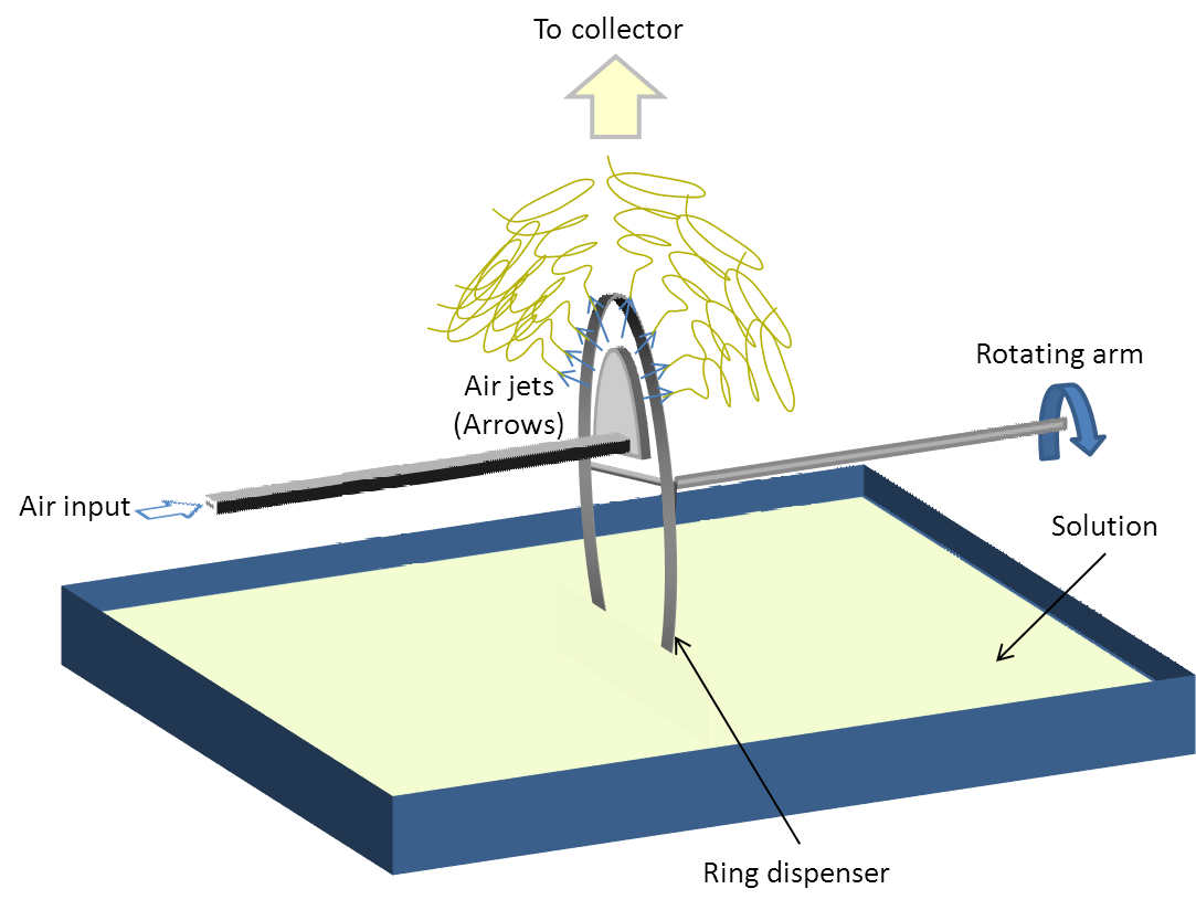
Using airflow to increase the production rate of electrospinning has been tested on needle-less electrospinning setup. Wang et al (2014) tested the effect of airflow on the production of electrospun fibers from a ring that rotates and dip into a solution reservoir (See figure 2 for illustration). Comparing the fiber production rate at different air flow rates, it was found that at lower air flow rate, the fiber production is lower than spinning without air flow. It was only at higher air flow rate that the fiber production rate is increased. At lower air flow rate, the solution coating on the circumference of the ring may be blown dry thus reducing the amount of available solution for jet initiation. At high air flow, the blowing air is sufficiently strong to stretch the polymer from the ring edge thereby faciliates jet initiation.
Centrifugal electrospinning (Read more) is another method to facilitate the electrospinning process. With centrifugal electrospinning, the concept is similar in the sense that the rotation of the nozzle will provide an initial stretching force on the solution which is later superseded by the electrical charges on the jet.
Figure 3 shows the characteristic of the forces on the electrospinning jet as it moves away from the nozzle. The initial thinning of the spinning jet may require a larger force to overcome the surface tension and inertia which is provided by the external force. Subsequently, a lighter but more uniformly distributed force from the charges on the electrospinning jet may be more effective in bringing the diameter of the fibers down to the nanometer scale without breaking the jet. Thus beyond a certain distance from the nozzle, the electrostatic force becomes the dominant force that replaces the external force in stretching the electrospinning jet.
In conventional electrospinning, the formation of Taylor cone for jet initiation comes from increasing accumulation of charges at an apex. As the Taylor cone is forming, more charges will accumulate at its tip until the repulsive force overcomes the surface tension of the solution and electrospinning commence. Facilitating jet initiation at a lower voltage can be achieved mechanically through artificially creating a sharp apex. This can be done by dipping a probe into the solution and pulling it off the surface of the solution. The resultant apex formed encourages accumulation of charges such that there is a momentary charge density where the repulsive force exceeds the surface tension and electrospinning is initiated. Chang et al (2008) used a tungsten probe tipto mechanically draw the solution at the tip of the needle to initiate electrospinning. In their study, this meant a reduction of electrospinning voltage from 1.5 kV (at tip to collector distance of 500 µm) to 600 V. The advantage of this concept has led Wu et al (2016) to term this, Tip-Induced Electrospinning (TIE) where they use an array of needles to initiate electrospinning off a free surface solution by dipping the needles into the solution and withdrawing them.
Published date: 03 March 2014
Last updated: 13 September 2016
▼ Reference
-
Ahmad B, Stride E, Stoyanov S, Pelan E, Edirisinghe M. Electrospinning of Ethyl Cellulose Fibres with a Heated Needle and Heated Air Using a Co-axial Needle: a Comparison. Journal of Medical and Bioengineering 2012; 1: 1
Open Access
-
Chang C, Limkrailassiri K, Lin L. Continuous near-field electrospinning for large area deposition of orderly nanofiber patterns. Appl Phys Lett 2008; 93:123111.
-
Peng M, Sun Q, Ma Q, Li P. Mesoporous silica fibers prepared by electroblowing of a poly(methyl methacrylate)/tetraethoxysilane mixture in N,N-dimethylformamide. Microporous and Mesoporous Materials 2008; 115: 562.
-
UM IC, Fang D, Hsiao B S, Okamoto A, Chu B. Electro-spinning and electro-blowing of hyaluronic acid. Biomacromolecules 2004; 5: 1428.
-
Wang X, Lin T, Wang X. Use of airflow to improve the nanofibrous structure and quality of nanofibers from needleless electrospinning. Journal of Industrial Textiles 2014. Article in press DOI: 10.1177/1528083714537100.
-
Wu D, Xiao Z, Deng L, Sun Y, Tan Q, Dong L, Huang S, Zhu R, Liu Y, Zheng W, Zhao Y, Wang L, Sun D. Enhanced Deposition Uniformity via an Auxiliary Electrode in Massive Electrospinning. Nanomaterials 2016; 6: 135.
Open Access
▲ Close list