Electrospun nanofibrous yarn has the potential to be used in various applications such as textile, sensors and implantable scaffolds. In contrast to setups for fabricating continuous yarn, fabricating finite length nanofibrous yarn generally requires simpler setup with less optimization requirements. Control of the fiber structure, dimension and distribution is also easier for finite length yarns which may be critical for some applications. As with most electrospinning process, the methods for fabricating finite length yarns may be based on mechanical means, electric field control or a combination of both.
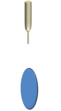
One of the earliest methods of constructing yarn is to use the rotating disk collector [Theron et al 2001]. This setup uses high rotation speed and the knife edge of the disk to guide the electrospinning jet to deposit fibers on the narrow edge. With sufficient fiber build-up, the yarn may be peeled off from the disk edge. The length of the yarn is restricted by the circumference of the disk. For greater fiber alignment, the rotation speed may be increased. However, it is not possible to increase the rotation speed indefinitely as this may cause fiber breakage or generate wind that blows the electrospinning jet away.
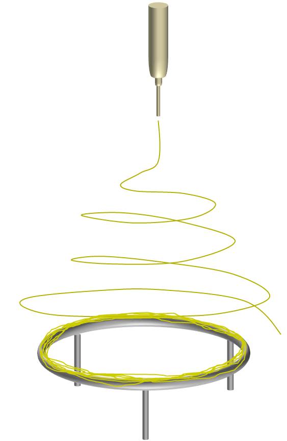
Where fiber alignment is not a concern, a single narrow collector will be able to direct the electrospinning jet to deposit fibers along the narrow length. Conceptually, this is similar to using a disk collector but stationary. Liu et al (2008) used an annular collector to prepare a short electrospun fiber yarn. A short length yarn bundle was collected and the fibers were observed to be randomly distributed. To generate fiber alignment, collected yarn bundle was pulled using a tensile tester. As the yarn bundle was relatively short, the fibers were able to align before significant breakages from the pulling force.
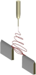
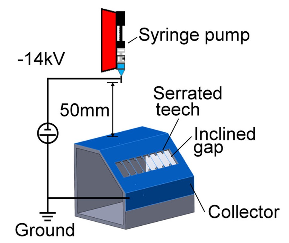
To obtain greater fiber alignment, the parallel electrodes collector concept may be used. Instead of using flat conductive electrodes, knife-edge electrodes are used and arranged with the length of the knife-edges aligned [Teo and Ramakrishna 2005]. This forces the fibers to be deposited within a narrow path forming a bundle. However, due to the presence of residual charges on the fibers, the individual fibers are separated by air gap. To consolidate the fibers, the bundle may be dipped in water and lifted off such that the water surface tension causes the fibers to consolidate into a tight and well-aligned fiber bundle. However, a limitation of this technique is that the length of the fiber bundle tends to be very short, about 5 cm. In an extension of the knife-edged parallel electrodes method for producing aligned fiber bundles, Hsu et al (2017) used a pair of serrated edges electrodes arranged in parallel to encourage multiple electrospun fiber bundles to form across the gap. The sharp points facing each other across the gap creates an electric field profile that encourages the electrospinning jet to jump between the tips. This resulted in the formation of multiple fibers bundles across the gap. However, the deposition duration was limited to 60s as longer duration and thicker fiber bundles formation disrupt the electric field profile leading to loss of fiber alignment.
Making use of parallel electrodes collector concept but extending the length of the yarn, a saw tip collector may be used. Chvojka et al (2013) used a custom made saw tip collector with free-surface electrospinning to collect fibers along the length of the collector. However, unlike the dual parallel electrodes collector, the fiber alignment on the saw tip collector was poor. Nevertheless, it allows for a longer length of nanofibrous yarn to be collected.
Parallel electrodes collector concept has also been used to fabricate twisted yarn. In this setup, the parallel electrodes have a larger surface facing each other. By rotating the electrodes in opposing direction relative to each other, fibers deposited on the electrodes are been twisted. This has been successfully used for fabricating short twisted fiber bundle for sensor application [Zheng et al 2015].
Fabrication of twisted fiber yarn bundle may also come from nanofibrous strips. These strips may be cut come from larger size nanofibrous membrane by conventional electrospinning. Although the strips are flat, twisting the strips at its ends will give rise to twisted yarn bundle [Zhou et al 2012]. This method is applicable to strips comprising of both randomly oriented fibers and aligned fibers.
Published date: 12 Jan 2016
Last updated: 20 March 2018
▼ Reference
-
Chvojka J, Hinestroza J P, Lukas D. Production of Poly(vinylalcohol) Nanoyarns Using a Special Saw-like Collector. Fibres & Textiles in Eastern Europe 2013; 21: 28.
Open Access
-
Hsu Y H, Chan C H, Tang W C. Alignment of Multiple Electrospun Piezoelectric Fiber Bundles Across Serrated Gaps at an Incline: A Method to Generate Textile Strain Sensors. Scientific Reports 2017; 7: 15436.
Open Access
-
Liu C K, Sun R J, Lai K, Sun C Q, Wang Y W. Preparation of short submicron-fiber yarn by an annular collector through electrospinning. Materials Letters 2008; 62: 4467.
-
Teo W E and Ramakrishna S. Electrospun fibre bundle made of aligned nanofibres over two fixed points. Nanotechnology 2005; 16: 1878.
-
Theron A, Zussman E and Yarin A L. Electrostatic field-assisted alignment of electrospun nanofibres Nanotechnology 2001; 12: 384.
-
Zheng J, Yan X, Li M M, Yu G F, Zhang H D, Pisula W, He X X, Duvail J L, Long Y Z. Electrospun Aligned Fibrous Arrays and Twisted Ropes: Fabrication, Mechanical and Electrical Properties, and Application in Strain Sensors. Nanoscale Research Letters 2015; 10: 475.
Open Access
-
Zhou Y, Fang J, Wang X, Lin T. Strip twisted electrospun nanofiber yarns: Structural effects on tensile properties. J. Mater. Res. 2012; 27: 537.
▲ Close list