Pros:
- Easy maintenance
- No clogged orifices
- High volume output
Cons:
- High voltage input required
- Difficult to maintain consistent solution concentration and viscosity.
- Potentially less uniform fiber diameter compared to the orifice technique.
On a still solution surface, the probability of the random movement of charges to gather at a point with sufficient density to initiate electrospinning is low. However, any disturbance to the solution surface that give rise to a temporary, high curvature point will cause a corresponding increase in charge concentration at that point which may be sufficient to initiate electrospinning.
Designs:
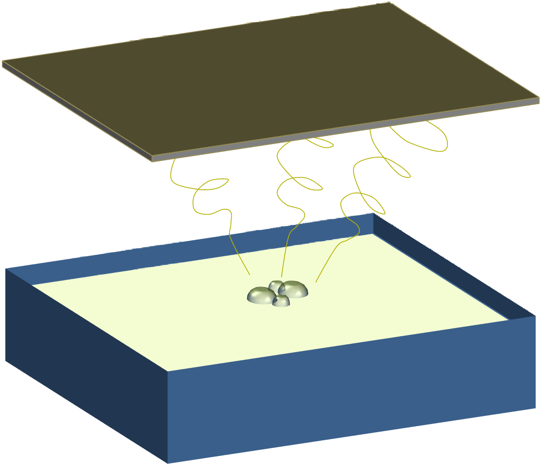
Bubble-surface disruption electrospinning
In this method, bubbles are blown into the solution. As the bubbles form on the surface, this creates a temporary protrusion on the otherwise still and flat solution surface. This temporarily increase the local charge density and electrospinning is initiated [Liu and He 2007; Varabhas et al 2009].
In a comparison between bubble electrospinning and free surface edge electrospinning using a bowl, Shao et al (2017) showed that edge electrospinning using a bowl has a higher polyvinyl alcohol (PVA) nanofiber throughput compared to bubble electrospinning. At the same applied voltage, the diameter was smaller and its consistency was better in edge electrospinning compared to bubble electrospinning. An electrical simulation of edge electrospinning and bubble electrospinning showed higher electric field intensity around the edge of the spinning reservoir while the presence of bubbles reduces the electric field intensity. This may explain the better performance of edge electrospinning. When compared with free surface electrospinning, bubble electrospinning did not fare better in terms of fiber output. The study by Fang et al (2019) showed that free surface electrospinning yield 6.28 g/h but bubble electrospinning was just 4.37 g/h. Although the average fiber diameter for bubble electrospinning was lower than from free surface electrospinning, its fiber diameter variation was greater. A possible reason for the lower production rate of bubble electrospinning could be the constant disruption of the electric field as the bubbles were formed and burst. Instead of having numerous stable spinning jets, the jets in bubble electrospinning have to undergo repeated Taylor Cone formation, jet ejection and termination.
Instead of using DC voltage in bubble electrospinning, high voltage AC has been found to increase the productivity of bubble electrospinning. Bubble electrospinning is a form of free surface electrospinning where air was forced through the solution to form bubbles on its surface. This surface disruptions in combination with a high voltage application encourages multiple electrospinning jets to erupt from each bubble. Erben et al (2020) hypothesized that using an AC high voltage with bubbling, there would be greater hydrodynamic disruption which encourages more electrospinning jet formation on the solution surface. Their experiment showed that the productivity of electrospun poly(vinyl alcohol) (PVA) fibers using AC bubble electrospinning is much higher than conventional DC bubble electrospinning at 2.0 g/h and 0.3 g/h respectively. The diameter of the fibers produced by AC bubble electrospinning is slightly lower than that of DC bubble electrospinning. Given similar fiber quality, the performance of AC bubble electrospinning is better than DC bubble electrospinning.
Ultrasonic agitation
Ultrasound may be used to create a solution protrusion in the center of a reservoir. The vibration generated by the ultrasound causes ripples to form on the solution surface from the edge and converge to the center of the reservoir creating a protrusion. This temporary protrusion is able to concentrate the applied electrical charges and initiates electrospinning. Nieminen et al (2018) demonstrated this method using polyethylene oxide (PEO). Their study showed that varying the acoustic power have an influence on the fiber diameter and diameter distribution. Less beads were found on fibers produced under low acoustic power but the fibers have larger diameter compared to those generated by high acoustic power. Hakkarainen et al (2019) did a comparison of chitosan and polyethylene oxide (PEO) fibers produced by ultrasonic agitation electrospinning and conventional nozzle electrospinning. Nanofibers produced by conventional nozzle electrospinning is thinner with average diameter of 77 nm compared to the fibers produced by ultrasonic agitation electrospinning with average diameter of 402 nm. Nozzle electrospinning also has lower diameter variation than ultrasonic agitation electrospinning. This is not surprising as free surface electrospinning does not restrain Taylor cone size and this contributes to larger and wider diameter distribution. With nozzle electrospinning, the constant nozzle diameter limits the size of the Taylor cone and this will reflect in the diameter of the resultant fibers assuming that no splitting of the jet occurs.
Published date: 18 Aug 2012
Last updated: 01 December 2020
▼ Reference
-
Erben J, Kalous T, Chvojkaac J. Ac Bubble Electrospinning Technology for Preparation of Nanofibrous Mats. ACS Omega 2020; 5: 8268.
Open Access
-
Fang Y, Xu L. Four self-made free surface electrospinning devices for high-throughput preparation of high-quality nanofibers. Beilstein J. Nanotechnol. 2019; 10: 2261.
Open Access
-
Hakkarainen E, Kõrkjas A, Laidmäe I , Lust A, Semjonov K, Kogermann K, Nieminen H J, Salmi A, Korhonen O, Haeggström E, Jyrki Heinämäki J. Comparison of Traditional and Ultrasound-Enhanced Electrospinning in Fabricating Nanofibrous Drug Delivery Systems. Pharmaceutics 2019; 11(10): 495.
Open Access
-
Liu Y, He J H. (2007) Bubble Electrospinning for Mass Production of Nanofibers. Int. J. Nonlinear Sciences and Numerical Simulations. 8 pp. 393.
-
Nieminen H J, Laidmae I, Salmi A, Rauhala T, Paulin T, Heinämäki J, Hæggström E. Ultrasound-enhanced electrospinning. Scientific Reports 2018; 8: 4437.
Open Access
-
Shao Z B, Yu L, Xu L, Wang M. High-Throughput Fabrication of Quality Nanofibers Using a Modified Free Surface Electrospinning. Nanoscale Research Letters 2017; 12: 470.
Open Access
-
Varabhas J S, Tripatanasuwan S, Chase G G, Reneker D H. (2009) Electrospun jets launched from polymeric bubbles. JEFF 4 pp. 46.
Open Access
▲ Close list
 ElectrospinTech
