Figure 1. Drawing yarn off solid substrate with assistance of an auxiliary electrode [Adapted from Dabirian et al 2007]
Most electrospinning setups used a solid substrate the collector for the electrospun fibers. To spin the collected fibers into yarn, the most direct method is to draw the deposited fibers directly onto a take-up unit during electrospinning. Dabirian et al (2007) spun polyacrylonitrile nanofibrous yarn by drawing electrospun nanofibers off a solid plate collector. A charged bar of opposing polarity was strategically placed between the solid plate collector and the take-up roller to encourage electrospun fibers to deposit directly on the yarn spanning the two as shown in the figure above. However, given that nanofibers are weak individually, the main challenge is to initiate the yarn take-up when bringing the deposited nanofibers to the take-up roller without breaking the yarn given that the adhesion of the nanofiber to a plate collector can be strong. A higher concentration which gives larger diameter fibers has been shown to facilitate continuous drawing of yarn off the solid substrate due to the added strength [Memarian et al 2014].
Figure 2. Yarn drawing off a modified solid substrate with a sharp edge funnel [Adapted from Xie et al 2015].
To reduce the adhesion between the fibers and the collector, a bowl or funnel collector with a sharp edge may be used [Afifi et al 2010, He et al 2013, Lee et al 2010]. With this collector, the fibers predominantly deposit on the edge. As the fiber layer builds up, the incoming fibers may be relatively loose and this facilitates drawing of the fibers off the edge. Using opposing charged electrospinning jets to deposit fibers on the rim of the bowl may facilitate fiber accumulation through charge neutralization [He et al 2013]. With sufficient build-up of fibers, later fiber deposits may adhere less strongly to the solid substrate even if it does not have a sharp edge and can be drawn off as yarn. Memarian et al (2014) was able to deposit TiO2 precursor fibers with opposing voltage onto an electrically earthed cylinder and drawn into a continuous yarn. Calcination of the precursor material gives TiO2 nanofibrous yarn.
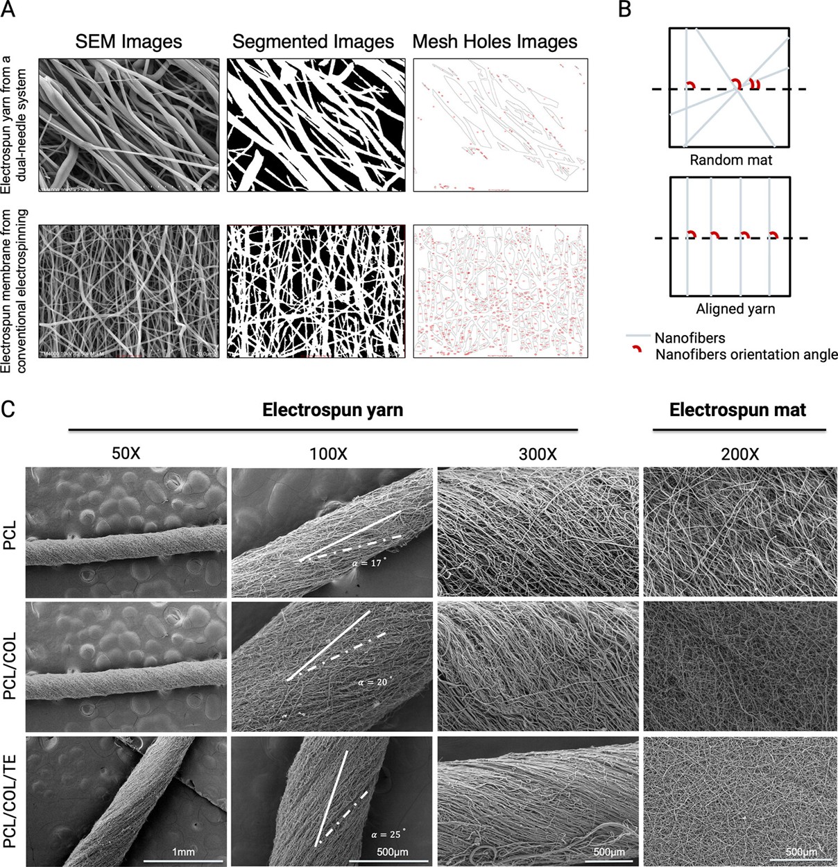
Zha et al (2025) et al used a grounded funnel to collect type 1 collagen (COL)/polycaprolactone (PCL)/tropoelastin (TE) fibers electrospun from two nozzles of opposing polarity. With the rotation of the grounded collection bowl, the yarn from the collector was twisted as it wound on a rotating arm wind up system. The resultant yarn was made of highly aligned nanofibers ranging from 400 nm to 800 nm with twist angle relative to the yarn axis ranging from 17° to 25°.
(A) The conversion of SEM images from a dual-needle system (Top line) and a conventional electrospinning system (Bottom line) to segmented images and mesh hole images using Diameter J image analysis software. (B) Schematic diagram showing how the nanofiber orientation angle was determined. (C) SEM images of the three electrospun yarns and the random electrospun mats [Zha et al 2025].
Focusing electrodes may be used to control the flight of the electrospinning jet as shown in Figure 2 such that most of the fibers are collected at the edge of the funnel [Xie et al 2015]. The collector may be rotated to add twist to the collected yarn [Afifi et al 2010]. In these setups where the electrospinning jet is between the solid substrate for temporary nanofiber collection and the take-up roller, the electrospinning jet may also deposit fibers on the take-up roller especially if the distance between the take-up roller and fiber collection substrate is not far enough [Yang et al 2014]. In this case, it may be necessary to shield the take-up roller from the electrospinning jet using a charged electrode that repels the fibers. The rotation of the collector, where the electrospinning jet first deposit, needs to be optimized to obtain maximum twist angle without breaking the yarn. Xie et al (2015) showed that with polyacrylonitrile nanofiber yarn, the funnel collector rotation speed was limited to 245 rpm as a higher rotation speed would break the yarn.
[Xie et al 2015]
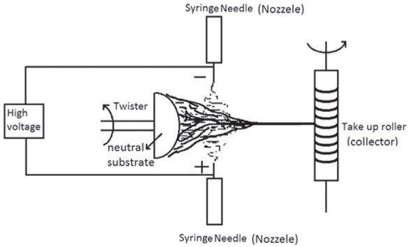
Minaei et al (2019) used opposing polarity electrospinning to deposit fibers on a neutral charge rounded surface collector. To form a twisted yarn, the collector was rotated as the yarn was drawn onto a take-up roller. Using this technique, they were able to produce electrospun casein/polyethylene-oxide (PEO) yarn. Observation under SEM showed a very low angle of twisting with most fibers aligned along the length of the yarn although numerous stray fibers were visible. Cross-linking using toluene di-isocyanate was used to strengthen the resulting yarn. In PBS, the cross-linked yarn completely degrades after 18 days.
Schematic of yarn electrospinning setup using opposing polarity [Minaei et al 2019].
Since drawing direction of the deposited fibers off the edge of the bowl is along the axis, the electrospinning jet needs to impact the edge of the bowl from the side. To increase the production rate, two rows of spinning jets with opposing charges may line along the circumference of the bowl. Twisting of the fiber yarn may be achieved by rotation of the collector or by passing the fiber bundle through a air twisting chamber. By varying the air jet orifice pressure, the twist angle on the yarn can be varied. He et al (2013) successfully constructed polyacrylonitrile yarn with twist angle ranging from 18.4° to 39.1° using this setup.
Passing the yarn through a air twisting chamber to impart a twist to the yarn
Ring collector for fabricating twisted yarn [adapted from Shuakat et al (2014)]
To further improve the yarn production rate, Shuakat et al (2014) used a ring collector design where fibers are deposited at one side of the ring and the yarn drawn out from the other side. Using this concept, high fiber production methods such as needless electrospinning and multiple nozzles electrospinning can be used to deposit fiber on one end of the ring without affecting yarn drawing from the other end. For the ring collector to gather fibers across the hole in the middle, Shuakat et al (2014) has to use both positive and negative voltage electrospinning such that the fibers are collected at the middle of the ring. Therefore, to generate fibers of both polarities when a high fiber production process is used on the underside of the ring, a single needle electrospinning with opposing polarity must be located on the upper side of the collector ring while yarn is being drawn from the upper side of the ring. At optimum condition, they are able to achieve a production rate of 0.068 m/s.
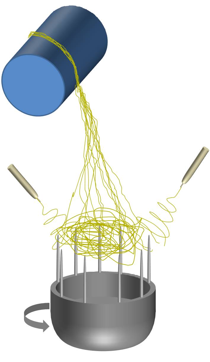
Illustration of yarn drawn from fiber deposited on sharp points [adapted from Joseph et al (2015)]
Reduction in contact and adhesion on the surface of the solid substrate will allow easier drawing of yarn from the fibers deposited on a solid substrate. A concept may be borrowed from the electrospinning of 3D fluffy fibers where the sharp points of pins pointing towards the electrospinning jet are used as collectors. Joseph et al (2015) used this concept to create a fluffy ball of nanofibers on the collector and the yarn is drawn to a spool. The collector comprises of sharp spokes evenly distributed around an axis and radiating towards the electrospinning spinnerets. Two spinnerets of opposing polarity were used for electrospinning fibers from the edge of the collector. To create a fluffy ball of nanofibers, electrospinning jet of opposing polarity is needed and the collector needs to be rotated. The opposing polarity is needed to cause collision of the electrospinning jet in mid-air. The rotation creates a pressure drop inside collector and the resultant inward airflow sucks the electrospun fibers to the center of the collector. The resultant fluffy fiber mesh is drawn into a yarn onto a spool while the rotation imparts a twist on the yarn.
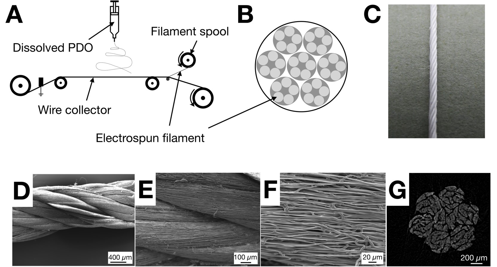
Instead of using pins or sharp edge bowls for collection of electrospun fibers prior to drawing onto a spool, a thin stainless steel wire may be used as the collector. Rashid et al (2020) used a moving thin stainless steel wire (100 µm diameter) under the electrospinning nozzle for collection of electrospun polydioxanone (PDO) fibers. The deposited fibers were then continuously drawn off the wire and onto a filament spool. The yarn from the spool made of electrospun fibers was sufficiently robust to be twisted into a suture. Scanning electron microscope (SEM) images showed that the yarn was made of well aligned fibers and the suture has an average diameter of 1.3 mm.
A) Schematic illustrating the setup for producing ES filaments (building blocks). B) Schematic of the ES multifilament suture structure produced through the two-step twisting process. C) Digital photograph showing a complete ES suture. D-F) SEM images showing the twisted multifilament ES suture at different magnifications: 50X (D), 250X (E) and 1000X (F). G) [Rashid et a; 2020]
In an interesting setup, a parallel electrode concept is used to collect continuous yarn. Two disks are placed orthogonal to each other such that deposited fibers on the circumference of the disk are aligned across the gap. Both disks are rotated where one provide the twisting effect while the other draws the fiber towards a winding collector [Bazbouz 2009]. During the drawing process, fibers aligned across the gap are continuously been twisted and pulled off the further disk edge as more fibers get laid across the gap. The twisting helps to consolidate the individual fiber strands and strengthen the resultant yarn which can be taken off the disk edge and rolled onto a bobbin. To use this setup, it is important that the electrospun fiber is strong enough to span over the gap and this is affected by the choice of polymer and the diameter of the fiber.
Yarn drawing off a modified solid substrate
Polymer
Solvent
Description
Take-up speed
Reference
Polyacrylonitrile (PAN)
N,N'-dimethylformamide
Twisted yarn
0.0039 m/s
Dabirian et al 2007
Polyacrylonitrile (PAN)
N,N'-dimethylformamide
Twisted yarn
0.0053 m/s
Xie et al 2015
Poly(L-lactide)
dichloromethane
Twisted yarn. Individual fiber diameter from 6 um.
Afifi A M, Nakano S, Yamane H, Kimura Y (2010) Electrospinning of Continuous Aligning Yarns with a 'Funnel' Target. Macromol. Mater. Eng. 295 pp. 660.
Bazbouz M B (2009) An investigation of Yarn Spinning from Electrospun Nanofibres. PhD Thesis. Heriot Watt University.
Open Access
Dabirian F, Hosseini Y, Ravandi S A H (2007) Manipulation of the electric field of electrospinning system to produce polyacrylonitrile nanofiber yarn. JITI 98 pp. 237
Joseph J, Nair S V, Menon D. Integrating Substrateless Electrospinning with Textile Technology for Creating Biodegradable Three-Dimensional Structures. Nano Lett. 2015 Article in press.
He J X, ZHou Y M, Qi K, Liu F J. Continuous nanofiber yarns twisted through three-dimensional high-speed swirling air flow. Thermal Science 2013; 17: 1269.
Open Access
Memarian F, Latifi M, Amani-Tehran M. Innovative method for electrospinning of continuous TiO2 nanofiber yarns: Importance of auxiliary polymer and solvent selection. Journal of Industrial and Engineering Chemistry 2014; 20: 1886.
Minaei F, Ravandi S A H, Hejazi S M, Alihosseini F. The fabrication and characterization of casein/PEO nanofibrous yarn via electrospinning. e-Polymers 2019; 19.
Open Access
Rashid M, Dudhia J, Dakin S G, Snelling S, Lach A, De Godoy R, Mouthuy P A, Smith R, Morrey M, Carr A J. Histological evaluation of cellular response to a multifilament electrospun suture for tendon repair. PLoS One 2020; 15(6): e0234982.
Open Access
Shuakat M N. Electrospinning of Nanofibre Yarns using Rotating Ring Collector. PhD Thesis 2014. Deakin University.
Open Access
Xie Z, Niu H, Lin T. Continuous polyacrylonitrile nanofiber yarns: preparation and dry-drawing treatment for carbon nanofiber production. RSC Adv. 2015; 5: 15147.
Yang C, Deng G, Chen W, Ye X, Mo X. A novel electrospun-aligned nanoyarn-reinforced nanofibrousscaffold for tendon tissue engineering. Colloids and Surfaces B: Biointerfaces 2014; 122: 270.
Zha D, Mahmood N, Kellar R S, Jessica M. Gluck J M, King M W. Fabrication of PCL Blended Highly Aligned Nanofiber Yarn from Dual-Nozzle Electrospinning System and Evaluation of the Influence on Introducing Collagen and Tropoelastin. ACS Biomater. Sci. Eng. 2025; 11: 6657.
https://pubs.acs.org/doi/full/10.1021/acsbiomaterials.5c00991 Open Access