Home | About | Contact


Mechanical Movement

Large-Align-fiber-mesh
Aligned nanofibrous mesh. (A) A4 size membrane showing silk-like reflection when it is curved (B). The aligned mesh is 1m wide and 3m long from MECC, Japan. [Teo et al STAM 2011, 013002]
Pros
  • Simple
  • Able to obtain a large area of aligned fibers
Cons
  • Fiber alignment is generally not as good as other technique
  • Fiber alignment is subjected to polymer and solution properties
Drum collector Roller belt collector
Rotating drum collector Belt collector

A rotating collector is one of the most popular methods of collecting oriented nanofibers. As the electrospinning jet travels towards the collector, the nanofibers are wound around the circumference of the rotating collector. This method is generally reliable in obtaining somewhat oriented fibers. However, the degree of fiber alignment is usually not as good as other techniques. There are several factors that may contribute to the difficulty of getting highly aligned fibers using this method. With the electrospinning jet hitting the surface of the collector at a high velocity, a faster rotation is required to coil the fibers in the direction of rotation. However, a higher rotation speed is likely to generate more wind and air turbulence that may "blow" the fibers away [Kim et al 2004]. Nevertheless, the drum design can be modified such that the amount of air turbulence is reduced. Another possible reason is the presence of charges on the deposited fiber [Sun et al 2012] which deflects the incoming fiber just before impacts the rotating collector. Kessick et al showed that by using an alternating current power supply instead of a DC power supply, membrane with a higher degree of fiber alignment can be constructed. This may be due to reduction in the chaotic movement of the electrospinning jet and charge neutralizing effect since both positive and negative charges are present [Kessick et al 2004].

For some solution, it is very difficult to get aligned fibers using a rotating drum. This may be due to low polymer strength which results in fiber breaking before it can be aligned. Necking has been observed on nanofibers collected on a rotating disc collector [Zussman et al 2003]. The electrospinning jet velocity may also be so high that the drum rotation speed is unable to match without generating excessive wind or breaking the fiber. Milleret et al (2011) showed that increasing the distance between the spinneret tip and the collector from 10 cm to 25 cm increases electrospun polyurethane alignment from 41% to 89%. Leach (2013) has also showed significant electrospun poly(L-lactide) fiber alignment when the distance between needle tip and collector increases with the best alignment at 30 cm distance. As electrospun fibers are light-weight, the velocity of the electrospinning jet may be reduced at a larger distance between the tip and the collector thus the drum collector is able to collect fibers with greater alignment. Increasing the distance or using a more volatile solvent will allow strengthening of the electrospinning jet through solvent vaporization which facilitates collection of aligned fibers if fiber necking or breakage was observed on the collected fibers [Leach 2013]. Another possible reason for the difficulty in obtaining aligned fibers is that the speed of the electrospinning jet is so fast that it is not possible to achieve sufficient rotation speed without generating excessive air turbulence. Krishnamoorthy et al (2011) constructed air-turbulance shield for collection of TiO2 precursor nanofibers on a rotating disk. With the air shield, they were able to collect better aligned fibers at the same rotation speed. The amount of fibers collected was also greater with the air-shield. Wind generated by high rotation speed of the collector generally creates air turbulence and may significantly reduce the amount of fibers collected. However, by deliberate placement of the rotating collector surface relative to the electrospinning jet, it is possible to reduce fiber lost to a minimum while maintaining a high speed of rotation.

Electrospinning with air shield
Fig 1. Rotating disk with (Left) enclosed-air-shield with air-hood (front view), (Right) air-hood arrangement (top view) for the turbulent air to escape [Krishnamoorthy et al Journal of Nanomaterials, vol. 2011, Article ID 739241, 7 pages, doi.org/10.1155/2011/739241. This work is licensed under a Creative Commons Attribution 3.0 Unported License.]
Electrospinning with air shield
Fig 2. The TiO2 ceramic nanofibres of diameter 98±20 nm were collected using the rotating disc at 750 rpm; (left) without air shield and (right) using enclosed-air-shield with air-hood. [Krishnamoorthy et al Journal of Nanomaterials, vol. 2011, Article ID 739241, 7 pages, doi.org/10.1155/2011/739241. This work is licensed under a Creative Commons Attribution 3.0 Unported License.]
liuetal2013a.jpg
liuetal2013.jpg
Fig 3. (Top) Centrifugal electrospinning setup schematic. (Bottom) Aligned polystyrene nanofibers constructed from centrifugal electrospinning with applied voltage of 3 kV, rotation at 420 rpm and distance between tip and collector of 2.5 cm [Liu S L et al. Journal of Nanomaterials, vol. 2013, Article ID 713275, 9 pages, doi:10.1155/2013/713275. This work is licensed under a Creative Commons Attribution 3.0 Unported License.]

Instead of having a rotating collector, the spinneret may be rotated instead in a method known as centrifugal electrospinning to create aligned fibers. With the introduction of centrifugal force, a lower voltage is required to overcome the surface tension of the solution to initiate electrospinning. The combination of mechanical rotation and the reduced voltage makes this a very effective method for fabricating aligned nanofibers [Liu et al 2013, Dabirian et al 2011, Edmondson et al 2012VR]. Highly aligned polystyrene nanofibers have been constructed using an applied voltage of 3 kV with a low rotation speed of 420 rpm [Liu et al 2013] as show in figure 3. Dabirian et al (2011) showed that with high rotation speed of more than 6000 rpm, the centrifugal-electrospun polyacrylonitrile solution jet travelled in a straight path towards the collector. Faster solvent evaporation of centrifugal electrospinning has also been credited for the observation of stable jet [Dabirian et al 2011].


centrifugal electrospinning
Fig 4. Centrifugal electrospinning with the jet spinning direction inline with the centrifugal force.

The direction of the nozzle exit relative to its spinning may effect fiber alignment from centrifugal electrospinning. In the setup by Liu et al (2013), the nozzle exit was pointing downwards while the centrifugal force was in the orthogonal direction. They were able to construct highly aligned nanofiber at a low rotation speed of 420 rpm. In the setup by Kancheva et al (2014), the nozzle exit was in the same direction as the centrifugal force. At a rotation speed of 1900 rpm, they were unable to get aligned fibers on the collector. Aligned fibers were only collected at gaps between parallel strips collector. Such difference may be due to the solution used with Liu et al (2013) using polystyrene solution and Kancheva et al (2014) using polyacrylonitrile solution. Another possible reason could be the direction of the spinning jet relative to the centrifugal force. When the jet spinning direction is orthogonal to the centrifugal force, the change in direction reduces the speed of deposition which allows the fibers to orientate in the direction of rotation. When the jet spinning direction is in the same direction as the centrifugal force, there is no reduction in the deposition speed. Instead, the deposition speed may increase and reduce the time available for fiber orientation. Controlled studies will be needed to test this hypothesis.

A high rotation speed will create a centrifugal force that throws objects in a direction normal and away from the rotating device. Tomaszewski et al (2012) used this concept to collect highly aligned nanofibers. Rotating a filter basket at speed of 30 m/s, they were able to obtain polyvinyl alcohol with satisfactory alignment. While electrospinning deposit fibers on the whole interior of the basket, only the fibers on the side wall of the basket is aligned. Although it is not specifically mentioned in the manuscript, it is likely that this setup will also significantly reduce the yield loss in obtaining aligned fibers due to the suction force that draws air from the top and expelled from the porous side wall. If this hypothesis is correct, it will be interesting to note whether the yield loss would increase when deposited fibers start to block out the pores at the side walls. Apart from using a rotating collector for direct collection of aligned fibers, another technique is to deposit the fibers on a water surface prior to collection.

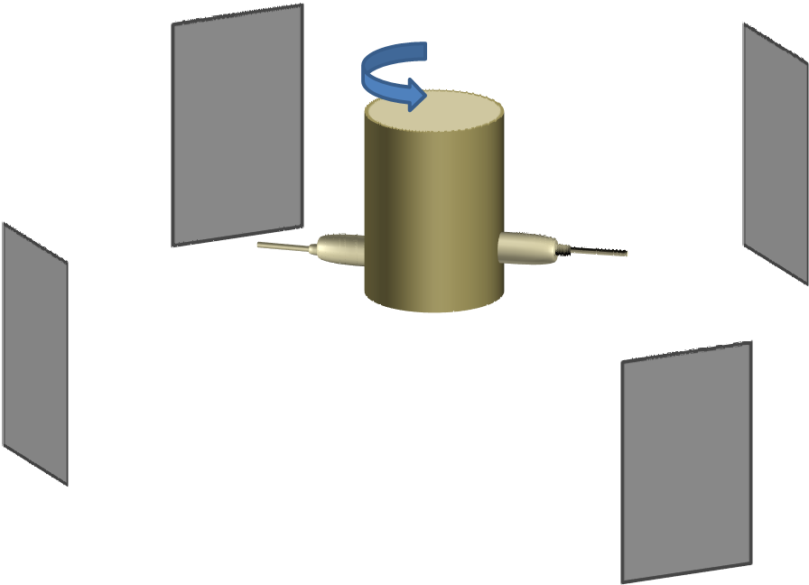
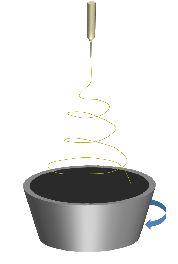
Fig 5. A variant of centrifugal electrospinning setup where a porous rotating bowl or cup is used to collect aligned fibers.


VR: Verification Required.Click here for verification procedure


Published date: 12 August 2012
Last updated: 29 October 2014


Comments
[+]


Google Ad.