Small diameter of electrospun nanofiber gave the resultant structure a high surface area to mass which makes it an excellent candidate to incorporate surface functionality or application where high surface area is desirable. To further increase the surface area, pores and dimples may be introduced to the surface of the nanofibers. Currently, the two methods to achieve this are by controlling spinning environment and solution interaction and by using sacrificial material. Such nanofiber morphology has been demonstrated both in as-spun polymer nanofibers and in sintered inorganic nanofibers. Studies have provided quantitative data on the extent of surface area increment on dimpled nanofibers compared to smooth fibers [Sharma et al 2014, Leong et al 2009].
Greater surface area of nanofiber for protein adsorption has been recommended for better cell adhesion and proliferation performance [Leong et al 2009]. Nanofibers with roughened or porous surface has been shown to adsorb 80% more proteins than smooth surface nanofiber scaffold after 24 h [Leong et al 2009]. A study comparing nerve cell cultured on roughened nanofiber and smooth nanofiber showed greater growth and proliferation in the former scaffold [Zamani et al 2013]. Senthamizhan et al (2018) showed that the presence of pores of electrospun cellulose acetate nanofibers gave greater protection to dithiothreitol capped gold nanocluster (DTT.AuNC). Cellulose acetate was first electrospun into fibrous membrane before immobilizing DTT.AuNC on its surface by dipping in a DTT.Au suspension followed by washing. Attachment of DTT.AuNC onto pCAF may be from the hydrogen bonding between the thiol (-SH) or hydroxyl group in DTT with acetate group of CA. It is interesting to note that DTT.AuNC immobilized on pCAF is more stable than DTT.AuNC immobilized on nonporous CAF. Greater stability of DTT.AuNC on pCAF may be due to deeper penetration of DTT.AuNC into the pores of pCAF and the protection of DTT.AuNC within its pores. When tested for detection of Cu2+, there is a visible detectable limit of 1 ppm with the membrane changing from red to blue for DTT.AuNC@pCAF under UV. Sensing response of DTT.AuNC on nonporous CAF to Cu2+ was much weaker.
In composite, surface topography of the filler fibers may also affect the interfacial compatibility with the matrix material. Xuan et al (2021) tested the effect of electrospun poly (L-polylactic acid) (PLLA) fibers with smooth and porous surface topography when embedded within a poly(methyl methacrylate) (PMMA) matrix. Comparing the light transmittance of the composite, pure PMMA has the highest transparency of 89% at wavelength of 589 nm. For PMMA composite containing smooth surface PLLA fibers, the transmittance drops to 80.16%. With porous fibers, the drop in transmittance was less and the composite containing the fibers with larger pores has a transparency of 88.72%. This is despite smooth surface fibers having the smallest diameter. The better light transmittance may be due to greater interfacial compatibility between the porous PLLA fibers and the PMMA matrix.
Membrane made of porous fiber increases its surface roughness and this in turn increases its hydrophobicity. Electrospun non-porous poly(lactic acid) (PLA) membrane has a water contact angle of 121° but electrospun porous PLA membrane at relative humidity of 80% has a water contact angle greater than 150°. The porosity of the PLA membrane increases from 81% to 92% when the environmental relative humidity for electrospinning increases from 40% to 80% due to increasing pores on the fibers. For the purpose of oil-water separation, Liu et al (2018) showed that with higher membrane porosity due to pores on the fibers and fiber diameter due to higher humidity, flux of the three model oils, n-hexane, olive oil and lubricant oil showed higher rate.
Two main hypotheses have emerged to explain the formation of pores on the electrospun fibers, breath figures [Casper et al 2004] and phase separation [Megelski et al 2002, Casper et al 2004]. Breath figures are pores formed by condensation of water droplets on the surface of the nanofibers during the electrospinning process. Since surface pores normally form when the humidity is high, it is possible that breath figures may be the cause of it. However, the introduction of water into the spinning jet may also result in phase separation and this may also give rise to porous fibers as they are generally non-water soluble [Megelski et al 2002].
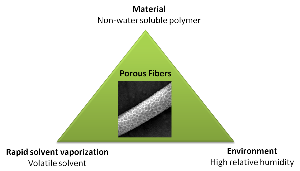
There are three factors to generate porous fibers in a high humidity environment. Apart from high humidity, a material that is non-water soluble is needed to respond to water condensation on the electrospinning jet and a volatile solvent to lock-in the feature. If the solvent evaporation is too slow, the formed feature would re-dissolve into the solution and a smooth fiber would form instead [ Nezarati et al 2013]. Regardless of whether the pore formation is due to breath figures or phase separation, these three factors need to be optimized to obtain porous fibers.
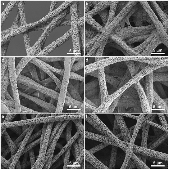
While it is difficult to say conclusively whether either theory or just one of the theories contributes to the formation of porous fiber, it has been demonstrated that solution tailored for phase separation during electrospinning is able to generate porous fibers. Lubasova et al [2011] defined three conditions for the fabrication of porous polyvinyl butyral nanofibers,
- Mixture of good and poor solvents
- Significant difference in the evaporation rate between the solvents
- Ratio of the good and poor solvent mixture
By controlling these three parameters, they are able to fabricate fibers with different pore profiles as shown in the figure. Theoretical approach for solvent selection is through application of Hansen solubility parameter and a two-dimensional graph and details may be found in Lubasova et al [2011]. McCann et al (2006) electrospun fibers directly into a cryogenic liquid to produce porous fibers through thermally induced phase separation. Presence of residual solvent was necessary for phase separation to occur for the creation of pores on the fibers. When the tip to collector distance was too high, complete evaporation of the solvent when the fibers hit the collector resulted in fibers with smooth surface. This method has been used to produce porous polystyrene, polycaprolactone, polyacrylonitrile and polyvinylidene fluoride.
Using a more volatile solvent for electrospinning has also been shown to result in fibers with surface pores. Celebioglu and Uyar (2011) demonstrated this effect when they electrospin cellulose acetate with dichloromethane (DCM) and acetone mixture. However, when the more volatile dichloromethane was replaced with less volatile N,N-dimethylacetamide, fibers without pores were produced. They hypothesized that fast vaporizing of DCM give rise to local phase separation which results in the pore formation. Cooper et al (2018) was able to electrospin biobased poly(butylene succinate) (BioPBS) porous fibers using CHCl3 as the solvent. CHCl3 is volatile with a boiling point of 61 °C. Instead of using breathe figures and phase separation to describe pore formation, Cooper et al (2018) suggest that pores were formed where region of relatively higher solvent content evaporated faster than the surrounding region.
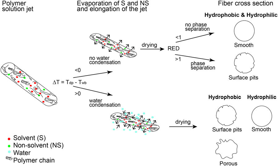
To predict the formation of pores and other surface morphological structures on the fibers. Various models have been developed. Yazgan et al (2017) conducted a series of tests on the influence of humidity, polymer solubility and water condensation due to temperature of polymer solution surface during electrospinning to come out with a working hypothesis to predict the formation of pits and surface structures on electrospun fibers. In a more volatile solvent, evaporation rate will be faster and this will favor rapid cooling of the fiber surface to a minimum temperature known as wet bulb temperature (Twb). When the surrounding air is cooled to full saturation, it reaches the dew point (Tdp) and water condenses on the surface. In agreement with other published reports, higher humidity tends to favor pits and grooves on fiber surfaces for hydrophobic polymers as demonstrated by PCL and PLLA while hydrophilic polymers give smooth surface fiber as demonstrated by PVP. This is due to Twb on the surface surface dropping below Tdp which causes water droplets to form pits on it, also known as breath figures. However, there are also cases where wrinkled fiber surfaces are formed without temperature dropping below Tdp. Phase separation due to solubility of the polymer in the solvent would account for it. Solubility may be determined by RED value which is the ratio of the coordinates' distance to the center of the sphere and the sphere's interaction radius of the molecule. RED value lower than 1 signifies higher solubility. Essentially, when RED is greater than 1, phase separation is more likely to occur resulting in a wrinkled fiber surface. It is also important to note that with water condensing or absorption into the solvent during electrospinning, the RED value may increase thereby inducing phase separation.
Zhang et al (2020) also developed an empirical model to predict the formation of morphological features on the surface or bulk of electrospun fibers based on a given solution and environmental condition. For their model, the polymer is assumed to be non-water soluble and the solvent has to be water-miscible or polar solvent for pore formation. An evaluation parameter in their equation is Cw, which measures the propensity for water condensation. When Cw >> 1, there is much water vapor condensation on the surface of the electrospinning jet. This will lead to the formation of peats, pore or phase separation either on the surface or the bulk of the polymer fiber. When Cw << 1, there is no water vapor condensation hence the polymer surface remains smooth. They hypothesised that with a less volatile polar solvent, water vapour that condensate on the fiber surface would have time to migrate into bulk and cause phase separation resulting in wrinkled fibers.
By using heated collector, the physical structure of the porous electrospun fibers can be modified. Kim et al [2006] found that the boiling point of the solvent and the Tg of the polymer influence the structure and the density of the pores on the fiber. It is known that as-spun fibers retain a certain level of residual solvent. On a heated collector, the evaporation of the residual solvent will be accelerated and this has the effect of enlarging the pores. At temperature greater than the boiling point of the solvent, the pore size reduces but more pores of smaller diameter were formed on the fiber surface. Above the Tg of the polymer, the edges of the pores may collapse creating smooth edged but smaller pores.
Heat application at the nozzle has also been shown to influence the characteristics of the pores on the electrospun fiber. Wildy et al (2024) investigated the effect of the application of heat to the electrospinning nozzle tip influenced pore formation on polystyrene (PS) fibers. Using a heat gun for direct heat blowing on the nozzle tip, electrospun PS fibers in N, N Dimethylformamide (DMF) exhibited porous surface structure for temperature less than 260 °C. At temperature above 300 °, the fibers were predominantly solid with a smooth surface. At high temperature, rapid solvent evaporation possibly limits the time needed for water condensation and phase separation. At temperature above the glass transition, the polymer molecules were at a more relaxed state and this may reduce the formation of polymer lean domains. Diameters of the electrospun fibers were reduced with a decrease in standard deviation. Using tetrahydrofuran (THF) as the solvent, the resultant fibers showed flat ribbon cross section with solid core at room temperature and increasing internal pores at temperatures greater than 150 °C. The porous interior may have been formed by thermally induced phase separation. Elliptical surface pores were found on electrospun fibers at room temperature but became circular at high temperature. This has been attributed to faster evaporation of solvents and reduced water condensation resulting in smaller pores solidifying in place.
Using a water bath as a collector introduces another method of modifying the electrospinning process to influence pore formation in the resultant fibers. Phase separation is one of the most common processes that drives the formation of pores in electrospun fibers and three common forms are thermally induced phase separation (TIPS), vapor-induced phase separation (VIPS), and non-solvent induced phase separation (NIPS). Utilising water bath as a non-solvent induced phase separation (NIPS) and it is important to select a solvent that is non-polar. A solvent that is miscible with water will allow near instantaneous entry of water into the jet and precipitation of the polymer. Using polystyrene (PS) and N,N-dimethyl formamide (DMF) as the solvent, the resultant electrospun PS fibers showed no surface pores [Zhu et al 2020]. However, when chlorobenzene (CB) was added into the PS in DMF solution with a CB/DMF ratio of 1:3, porous fiber was produced. This is due to CB being immiscible with water and this encourages phase separation to occur within the fiber. As the electrospinning jet enters the water bath, the water being a non-solvent initiate phase separation with polymer-rich and polymer-poor regions. Nucleation and growth resulted in the formation of numerous, interconnected pores. When the water bath was heated to 40°C, the pore size started to decrease. This is probably due to reduced time available for nucleation.
An alternative mechanism to phase separation has been proposed for pore formation on electrospun fibers deposited on a water bath. Prasad et al (2020) has found that PVDF dissolved in N,N-dimethylformamide (DMF)/acetone solvent system of ratio from 30 to 50% DMF was able to give rise to porous fiber when electrospinning and depositing in water. However, the same solution when deposited in aluminium foil did not show fiber surface porosity. It was proposed that water was absorbed into the fibers after deposition on the water. During drying, the excess absorbed water was evaporated and this left behind pores on the fiber surface. With a higher percentage of DMF in the solvent system, the collected fibers get smoother with less pores. Since DMF has a higher boiling point than water, a greater amount of DMF may remain during electrospinning resulting in greater surface absorption of water on the fibers. A more uniform water absorption across the surface of the fiber may favor smoother fibers production.
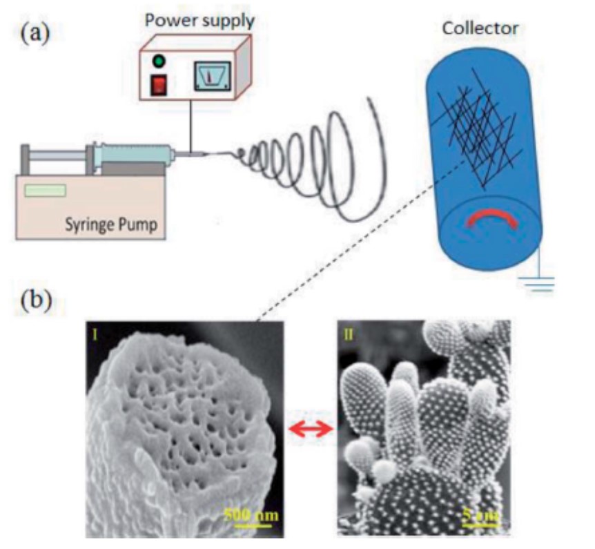
The influence of humidity and phase separation on the morphology of electrospun fibers go beyond the formation of surface pores. Other interesting fiber surface topography have also been reported with increasing humidity. Zaarour et al (2018) showed that electrospun polyvinylidene fluoride (PVDF) nanofibers with cactus-like surface topography can be constructed. Using a mixture of acetone (ACE) and N,N-dimethylformamide (DMF) as solvents, fibers with cactus-like surface topography can be electrospun at relative humidity above 40%. They attributed the formation of protrusions from the accumulation of acetone vapour trapped beneath the solidified skin of PVDF in high humidity. High humidity and water condensation on the surface of the fiber during eletrospinning causes rapid precipitation of PVDF and forming a skin layer. The accumulated trapped vapour pushes the skin at various points on the fiber, creating protrusions on the surface which were later closed up as water on the surface caused precipitation at the exit points. The escaped vapours would also leave behind pores within the fiber core.
The rate of solvent evaporation is known to play a role in pore formation. The specific surface area of the electrospinning jet given by its diameter would influence the rate of solvent evaporation. A smaller electrospinning jet diameter will have a faster solvent evaporation rate. Liang et al (2019) showed that the pore size on electrospun fibers varies with the nozzle diameter. When the nozzle diameter increases, the pore sizes on the electrospun fibers decreases. This has been attributed to slower solvent evaporation when nozzle diameters are larger which lead to larger electrospinning jet. When the nozzle diameter is smaller, the narrower electrospinning jet and its corresponding higher surface area encourages faster solvent evaporation leading to larger pore size.
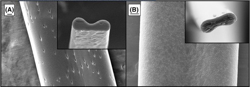
Christ et al (2022) observed that the boiling point of the solvent may have an influence on the shape of the pores on the fiber surface. With electrospun poly methyl methacrylate (PMMA) in different solvents, dichloromethane (DCM) and trichloromethane with their lowest boiling points in the group produces solid fibers with a porous surface. Between the two solvents, DCM has a lower boiling point than trichloromethane and round pores were observed. For trichloromethane, the pores were more elliptical. Christ et al (2022) suggested that faster evaporation of DCM meant that the pores formed on the surface of the jet do not have enough time to deform as it stretches. Since trichloromethane has a higher boiling point, slower solidification of the area surrounding the formed pore allowed it to be stretched.
Varying the feedrate of inorganic precursor and polymer solution has been shown to affect the fiber morphology of the sintered nanofiber. Lower feedrate for electrospinning tin(IV) acetate and polyvinyl acetate results in smooth surface and solid fibers while increasing feedrate leads to porous and thin walled SnO2 assemblies after sintering. Following incorporation of Pt on both fiber assemblies, the porous and thin walled SnO2 assembly showed five-fold higher acetone responses than the solid smooth surface fibers. The reason for this difference in morphology has been attributed to greater absolute volume of solvent at high feedrate which subsequently induces greater phase separation and thus giving rise to the thin-walled and porous structure [Shin et al 2012]. Controlling the processing environment and solution composition is the most common method for introducing pores on electrospun fiber surface. However, this limits the type of solution that can be used to produce porous fibers.
Using a sacrificial material reduces the dependence on environment-solution interaction. This method has been used in creating pits, pores and cavities in both inorganic and organic fibers.
For polymer fibers, a sacrificial material is blended with the desired material in solution form and electrospun into fibers. A solvent which the desired material is insoluble in is used to wash away the sacrificial material. The most common combination is to use a water soluble polymer for blending with a non-water soluble base material. In an attempt to create porous poly (l-lactide) (PLLA) electrospun fibers, Lu et al (2021) used cellulose acetate butyrate (CAB) as the sacrificial material. Following electrospinning to form fibers, acetone was used to remove CAB leaving behind porous PLLA fibers. However, the amount of CAB to PLLA blend concentration needs to be optimized. With low CAB concentration (PLLA/CAB (12/1)), porous PLLA fibers were formed. With increasing CAB concentration, the fibers start to collapse and lose their form after CAB is removed.
For some polymers, solvent-induced recrystallization may be used to generate pores on the fibers. Lu et al (2021) successfully demonstrated this using electrospun poly (l-lactide) (PLLA) fibers. With PLLA, acetone was found to cause swelling of the electrospun fibers. Pure electrospun PLLA fibers without any treatment exhibited low crystallization. However, when immersed in ethanol/acetone mixture, the crystallinity of the PLLA fibers increased with increasing acetone concentration with four distinct peaks in XRD diagrams at 50% acetone mixture. However, to induce rapid crystallinity rate, pure acetone was used. This causes the PLLA fibers to swell quickly which gives free spaces for molecules to rearrange and form crystalline phases. With greater packing of the polymer chains, pores are formed both inside and on the surface of the fibers. The electrospun PLLA fibers were only dipped in acetone for 5 min for pores formation.
Sacrificial nanoparticles made out of polystyrene may be mixed with a precursor solution for electrospinning. Sintering is subsequently carried out to remove the polystyrene nanoparticles which leave behind holes on the resultant fiber. This has been successfully used to fabricate porous silica fibers [Lim et al 2007, Wu et al 2014]. Birajadar and Lee (2015) demonstrated another method of producing pits on electrospun nanofibers. Electrospinning and electrospraying are carried out simultaneously using opposing high voltage such that silica nanoparticles adhere to the surface of polystyrene nanofibers. The resultant composite is heated to 120 °C so that the nanoparticles are embedded into the nanofibers surface. To remove the nanoparticles, the composite is immersed in water and ultra-sonicated for 60 minutes. The dislodged nanoparticles leave behind pits and craters on the surface of the polystyrene fiber.
Using a sacrificial material with the main fiber matrix material is a very versatile method to create porous fibers. Liu et al (2021) was able to combine the technique of core-shell electrospinning and incorporating a sacrificial material on the shell of the fiber to create hollow porous microfibers. To electrospin hollow porous polybutylene adipate terephthalate (PBAT) microfibers, a co-axial nozzle was used in the electrospinning. The outer solution was PBAT and low molecular weight polyethylene glycol (PEG) with PEG as the sacrificial material. The core sacrificial material was polyvinyl acetate (PVA) solution. After electrospinning, the core-shell fibers were ultrasonicated in pure water at 70°C for 12 h to dissolve the PEG and PVA. The resultant fibers have a hollow core with porous walls. With the increased surface area of hollow porous PBAT fibers compared to solid PBAT fibers, loading of polypeptide by surface adhesion onto hollow porous PBAT fibers was twice that of solid fibers. The degradation rate of hollow porous PBAT was also faster with 50% weight loss at 12 days while the solid PBAT fiber took more than 20 days to reach 50% weight loss.
Published date: 13 November 2013
Last updated: 15 October 2024
▼ Reference
-
Birajdar M S, Lee J. Nanoscale Bumps and Dents on Nanofibers Enabling Sonication-Responsive Wetting and Improved Moisture Collection. Macromol. Mater. Eng. 2015, DOI: 10.1002/mame.201500155 Article in press
-
Casper C L, Stephens J S, Tassi N G, Chase D B, Rabolt J F. Controlling Surface Morphology of Electrospun Polystyrene Fibers: Effect of Humidity and Molecular Weight in the Electrospinning Process. Macromolecules 2004; 37: 573.
-
Celebioglu A, Uyar T. Electrospun porous cellulose acetate fibers from volatile solvent mixture. Materials Letters 2011; 65: 2291.
-
Christ H A, Ang P Y, Li F, Johannes H H, Kowalsky W, Menzel H. Production of highly aligned microfiber bundles from polymethyl methacrylate via stable jet electrospinning for organic solid-state lasers. Journal of Polymer Science 2022; 60: 715.
Open Access
-
Cooper C J, Mohanty A K, Misra M. Electrospinning Process and Structure Relationship of Biobased Poly(butylene succinate) for Nanoporous Fibers. ACS Omega, 2018; 3 (5): 5547.
Open Access
-
Kim C H, Jung Y H, Kim H Y, Lee D R, Dharmaraj N, Choi K E. Effect of Collector Temperature on the Porous Structure of Electrospun Fibers. Macromolecular Research 2006; 14: 59.
-
Leong M F, Chian K S, Mhaisalkar P S, Ong W F, Ratner B D. Effect of electrospun poly(D,L-lactide) fibrous scaffold with nanoporous surface on attachment of porcine esophageal epithelial cells and protein adsorption. J Biomed Mater Res 2009; 89A: 1040
-
Liang J W, Prasad G, Wang S C, Wu J L, Lu S G. Enhancement of the Oil Absorption Capacity of Poly(Lactic Acid) Nano Porous Fibrous Membranes Derived via a Facile Electrospinning Method. Appl. Sci. 2019; 9(5): 1014.
Open Access
-
Lim J M, Yi G R, Moon J H, Heo C J, Yang S M. Superhydrophobic Films of Electrospun Fibers with Multiple-Scale Surface Morphology. Langmuir 2007; 23: 7981.
-
Liu Y, Yang L, Chen G, Liu Z, Lu T, Yang Y, Yu J, Kang D, Yan W, He M, Qin S, Yu J, Ye C, Luo H. PBAT hollow porous microfibers prepared via electrospinning and their functionalization for potential peptide release. Materials & Design 2021: 207: 109880.
Open Access
-
Liu Z, Zhao J, Xing J, Xu L, He J. Humidity-induced porous poly(lactic acid) membrane with enhanced flux for oil-water separation. Adsorption Science & Technology 2019 Article in press.
Open Access
-
Lu Z, Zhang B, Gong H, Li J. Fabrication of hierarchical porous poly (l-lactide) (PLLA) fibrous membrane by electrospinning. Polymer 2021; 226: 123797.
Open Access
-
Lubasova D, Martinova L. Controlled Morphology of Porous Polyvinyl Butyral Nanofibers. Journal of Nanomaterials 2011; 2011: 292516.
Open Access
-
McCann J T, Marquez M, Xia Y. Highly porous fibers by electrospinning into a cryogenic liquid. J. Am. Chem. Soc. 2006; 128: 1436.
-
Megelski S, Stephens J S, Chase D B, Rabolt J F. Micro- and Nanostructured Surface Morphology on Electrospun Polymer Fibers. Macromolecules 2002; 35: 8456.
-
Nezarati R M, Eifert M B, Cosgriff-Hernandez E. Effects of Humidity and Solution Viscosity on Electrospun Fiber Morphology. Tissue Eng Part C Methods. 2013; 19: 810.
Open Access
-
Prasad G, Liang J W, Zhao W, Yao Y B, Tao T, Liang B, Lu S G. Enhancement of solvent uptake in porous PVDF nanofibers derived by a water-mediated electrospinning technique. Journal of Materiomics 2020 Article in press.
Open Access
-
Senthamizhan A, Celebioglu A, Balusamy B, Uyar T. Immobilization of gold nanoclusters inside porous electrospun fibers for selective detection of Cu(II): A strategic approach to shielding pristine performance. Scientific Reports 2018; 5: 15608.
Open Access
-
Sharma C S, Haridas A, Rao T N, Sritharan V. Fabrication and Surface Functionalization of Electrospun Polystyrene Submicron Fibres with Controllable Surface Roughness. RSC Adv 2014 In press.
-
Shin J, Choi S J, Lee I, Youn D Y, Park C O, Lee J H, Tuller H L, Kim I D. Thin-Wall Assembled SnO 2 Fibers Functionalized by Catalytic Pt Nanoparticles and their Superior Exhaled-Breath-Sensing Properties for the Diagnosis of Diabetes. Adv. Funct. Mater. 2012; 23: 2357.
-
Wildy M, Wei W, Xu K, Schossig J, Hu X, Hyun D C, Chen W, Zhang C, Lu P. Heat's Role in Solution Electrospinning: A Novel Approach to Nanofiber Structure Optimization. Langmuir 2024; 40 (15): 7982.
Open Access
-
Wu C, Yuan W, Al-Deyab S S, Zhang K Q. Tuning porous silica nanofibers by colloid electrospinning for dye adsorption. Applied Surface Science 2014; 313: 389.
-
Xuan H, Wei S, Xiong F, Zhang Z, Xue Y, Sun M, Li B, Yuan H. Design of porous and fish scale-like nanofibers for the reinforcement of transparent composites. Materials & Design 2021; 212: 110284.
Open Access
-
Yazgan G, Dmitriev R I, Tyagi V, Jenkins J, Rotaru G M, Rottmar M, Rossi R M, Toncelli C, Papkovsky D B, Maniura-Weber K, Fortunato G. Steering surface topographies of electrospun fibers: understanding the mechanisms. Scientific Reports 2017; 7: 158.
Open Access
-
Zaarour B, Zhu L, Huang C, Jin X. Fabrication of a polyvinylidene fluoride cactus-like nanofiber through one-step electrospinning. RSC Adv., 2018, 8, 42353.
Open Access
-
Zamani F, Amani-Techran M, Latifi M, Shokrgozar M A. The influence of surface nanoroughness of electrospun PLGA nanofibrous scaffold on nerve cell adhesion and proliferation. Journal of Mdaterials Science: Materials in Medicine 2013; 24: 1551.
-
Zhang D, Davoodi P, Li X, Liu Y, Wang W, Huang Y Y S. An empirical model to evaluate the effects of environmental humidity on the formation of wrinkled, creased and porous fibre morphology from electrospinning. Sci Rep 10, 18783 (2020).
Open Access
-
Zhu L, Zaarour B, Jin X. Direct generation of electrospun interconnected macroporous nanofibers using a water bath as a collector. Mater. Res. Express 2020; 7: 015082
Open Access
▲ Close list