Electrospinning can be used to produce different structures by modifying its setup. A renewed interest in this process in the late 1990s comes from the realisation of the resemblance of electrospun nanofibrous scaffold to biological extracellular matrix (ECM). This has led to the development of electrospun tubular structures for small diameter vascular grafts and nerve conduits.
There are two main methods for the production of electrospun tubes. The first is to coat the nanofibers on a rod template followed by extraction of the tube. The second method is to first build a nanofibrous membrane followed by rolling the membrane into a tube form. Both methods may be used to fabricate tubes comprising of randomly oriented fibers and circumferentially aligned fibers. As for tube comprising of axially aligned fibers, it is usually made from rolled up membrane.
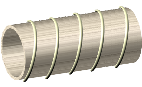
For clinical application of electrospun tube, it is necessary for it to have adequate mechanical strength. A consideration for biological graft is its suture retention strength. This has been tested by Meng et al (2019) on electrospun poly(L-lactide-co-caprolactone) P(LLA-CL) vascular grafts. P(LLA-CL) was selected as it is a known biodegradable and biocompatible material. Graft property such as fiber orientation, thickness and number stitches were examined. As expected, electrospun tube with circumferentially aligned fibers have the highest suture retention strength, followed by randomly aligned fibers and with axially aligned nanofibers being the weakest. Electrospun tube has also been strengthened by incorporating microfiber coil or mesh. To imitate the structure of trachea, Hung et al (2014) used 3 mm and 1.5 mm diameter flexible PLLA wire to coil around metal rod with 1.5 cm diameter and 0.5 cm diameter respectively with regular spacing between each coil. A thin layer of dichloromethane was applied on the PLLA wire coil to facilitate adhesion between electrospun fibers coated over the PLLA coil. The resultant hybrid tube is physically similar to native trachea and demonstrated good resistance to radial compression that exceeds that of native trachea. For construction of a hybrid tube with microfibers wound externally over electrospun fibers, Centola et al (2010) used fused deposition to wind a coil of polycaprolactone on the outer surface of an electrospun tube. Liu et al (2015) constructed a tri-layer tube with a micro-imprinted poly-p-dioxanone (PPDO) middle layer sandwiched between electrospun chitosan/polyvinyl alcohol layers. The PPDO layer provides the mechanical support while the electrospun layers provide a favourable environment for cell proliferation. Comparison of the mechanical properties showed significantly better tensile strength and radial strength at 19.8 MPa and 128 KPa respectively for the tri-layer tube with comparable specimen thickness to electrospun only tube.
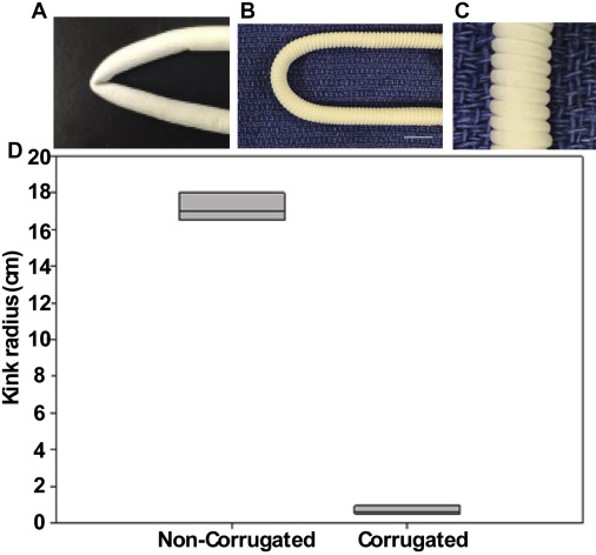
In clinical application of vascular graft a physical factor to consider is the non-kinking after it has been implanted. Commercially available grafts are mostly rigid and easily kink when implanted. Matsushita et al (2020) formed corrugation on a tube made of co-electrospun electrospun poly(L-lactide-co-caprolactone)/poly-ε-caprolactone (PCL/PLCL) nanofibers so that the corrugated tube is able to resist kinking. Such corrugation was formed by wrapping a monofilament around the electrospun tube, longitudinally compressed and allowing it to set for 24 h before the tube was relaxed and the filament removed. The ability of the tube to resist kinking was demonstrated by measuring its kink radius with a smaller radius having a greater resistance to kinking. Noncorrugated electrospun tubes had a kink radius 16 times greater than corrugated tubes.
Published date: 17 September 2019
Last updated: 06 October 2020
▼ Reference
-
Centola M, Rainer A, Spadaccio C, Porcellinis S, Genovese J A, Trombetta M. Combining electrospinning and fused deposition modeling for the fabrication of a hybrid vascular graft. Biofabrication 2010; 2: 014102.
-
Hung S H, Chen P Y, Tai C C, Chou C H, Cheng W L, Tseng H. Development of Tracheal Scaffolds Using Hybridization of PLLA Coil Skeleton and Electrospun Structures. J. Med. Biol. Eng. 2014; 34: 218.
-
Liu Y, Xiang K, Chen H, Li Y, Hu Q. Composite vascular repair grafts via micro-imprinting and electrospinning. AIP Advances 2015; 5: 041318.
Open Access
-
Matsushita H, Inoue T, Abdollahi S, Yeung E, Ong C S, Lui C, Pitaktong I, Nelson K, Johnson J, Hibino N. Corrugated nanofiber tissue-engineered vascular graft to prevent kinking for arteriovenous shunts in an ovine model. JVS: Vascular Science 2020; 1: 100.
Open Access
-
Meng X, Wang X, Jiang Y, Zhang B, Li K, Li Q. Suture retention strength of P(LLA-CL) tissue-engineered vascular grafts. RSC Adv. 2019; 9: 21258.
Open Access
▲ Close list